
Invisible appliance with pressure accessory and making method thereof

A technology for invisible appliances and accessories, which is used in medical science, dentistry, orthodontics, etc., can solve the problems of uneven depth, falling off of bonded solid accessories, and inability to control the concave depth of the accessory cavity, and achieve the concave depth. controllable effect

Active Publication Date: 2017-02-22
杭州一牙数字口腔有限公司
View PDF11 Cites 9 Cited by
  • Summary
  • Abstract
  • Description
  • Claims
  • Application Information

AI Technical Summary

Problems solved by technology

Commonly used solid attachments include oval attachments and rectangular attachments. The disadvantage of using solid attachments is that the physical attachments need to be bonded and fixed on the crown, which is likely to cause damage to the crown enamel. If the bonding is not strong, the physical attachments will fall off
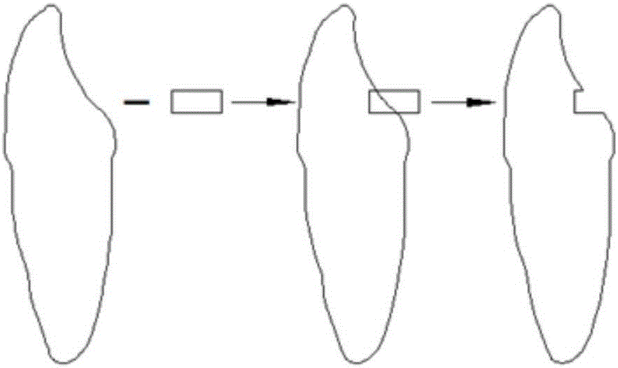
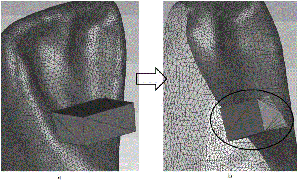
The disadvantage of this manufacturing method is that the crown is an irregular surface whose thickness decreases from the root to the top of the tooth, and the size of the crown of each tooth is different. The attachment obtained by Boolean subtraction between the attachment model and the crown surface The cavity cannot control the recessed depth of the accessory cavity, often some places are deep and some places are shallow, such as image 3 As shown, in the invisible aligner made in this way, the depth of the raised cavity on it is not uniform, so that the resultant direction of the aligning force of the aligner on the teeth will be deflected (such as Figure 4 shown), and the correction force deviates from the theoretically calculated correction force, and the correction force is uncontrollable, which affects the correction effect

Method used


Image

  • Invisible appliance with pressure accessory and making method thereof
  • Invisible appliance with pressure accessory and making method thereof
  • Invisible appliance with pressure accessory and making method thereof

Examples


Embodiment Construction

[0024] Such as Figure 10 Shown, the manufacture method of the invisible aligner with pressure attachment comprises the following steps:

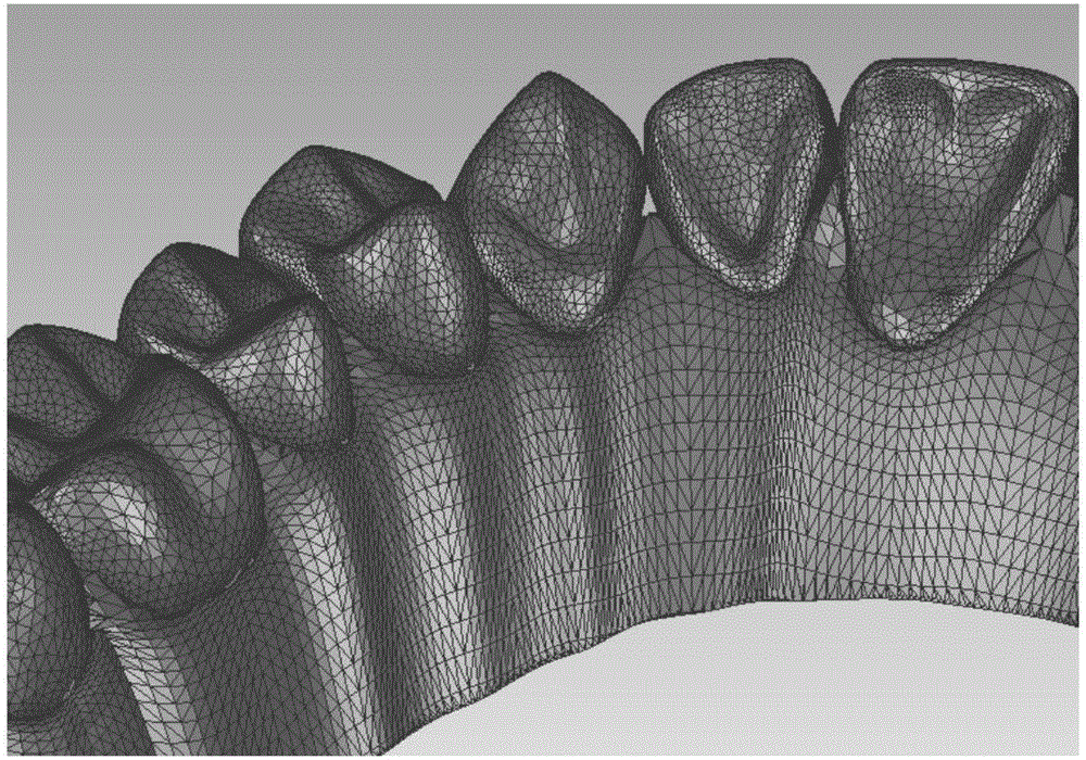
[0025] 1) Perform three-dimensional reconstruction of the patient's dental model to obtain the patient's digital dental model. The digital dental model is represented by a triangular mesh, such as figure 1 shown. The data format of the digital dental model generally uses the STL format. The STL format uses a triangular mesh to approximate the surface model. The smaller the triangular mesh is compared to the overall size of the model, the higher the fit between the STL model and the actual model, and vice versa. Then the error is bigger.

[0026] 2) Select a crown that needs to be installed with accessories as the current crown, select the area where the accessories need to be installed on the surface of the current crown, and refine the triangular mesh of the selected area. The goal of triangular mesh refinement is that the refined tria...


PUM


Abstract

The invention relates to an invisible appliance with a pressure accessory and a making method thereof. The method consists of: acquiring a digital dental model of a patient; selecting a current dental crown, selecting an area needing to install accessory, and refining triangular meshes of the selected area; selecting an accessory cover area in the mesh refined selected area, and making all the triangular meshes in the accessory covered area deviate to the inside of the dental crown by an equal distance so as to obtain a uniform depth accessory cavity concave into the dental crown; and moulding the digital dental model into an entity dental model hot-press film, thus obtaining the invisible appliance. The invisible appliance with the virtual accessory includes a body, the tooth positions of the body and the of a patient are in one-to-one correspondence, several tooth positions of the body have bulges, the tooth positions with bulges match with the patient's dentural teeth needing the pressure accessory, in the direction from the tooth crest to the tooth root, the bulges have uniform thickness. The accessory equipped invisible appliance provided by the invention can provide accurate orthodontic force.

Description

technical field [0001] The invention relates to an invisible aligner and a manufacturing method thereof. Background technique [0002] Bracket-free invisible orthodontic technology uses computer 3D reconstruction, aided diagnosis design technology and computer manufacturing technology to design and manufacture a series of orderly transparent removable appliances, and use the elastic force generated by the elastic deformation of the appliance itself to realize dental and jaw deformities of correction. It is a continuous and orderly orthodontic device, which achieves the purpose of orthodontics through continuous small-scale tooth movement. Because of the way the clear aligner contacts the teeth, the way the teeth move is somewhat difficult to achieve. For example: elongation movement of teeth, movement control of columnar teeth, twisting of mandibular premolars, etc. In order to solve these problems, the non-bracket invisible orthodontic technology introduces the auxiliary...

Claims


Application Information

Patent Timeline
Patent Type & Authority Applications(China)
IPC IPC(8): A61C7/00
Inventor 朱彤
Owner 杭州一牙数字口腔有限公司
Learn More