Convex/concave pattern-forming stamp, convex/concave pattern-forming method and magnetic recording medium

A technology of concave-convex pattern and embossing mold, which is applied in the manufacture of record carriers, the support of paint carriers, and the device for coating liquid on the surface, etc., can solve the problems of uneven depth of concave parts, deformation and peeling of track formation areas, etc.

Inactive Publication Date: 2007-02-14
TDK CORPARATION
View PDF4 Cites 0 Cited by
  • Summary
  • Abstract
  • Description
  • Claims
  • Application Information

AI Technical Summary

Problems solved by technology

Therefore, if Figure 20 As shown, the concave-convex pattern forming region 104 in the outer peripheral portion 104b and the inner peripheral portion 104c is formed with a depth of concave portion (the height of the convex portion) that is deeper than the concave portion depth formed in the central portion 104a of the concave-convex pattern forming region 104 (than the height of the convex portion). The height is high), finally, there is a problem that the depth of each concave part is not uniform
Because the pressure is concentrated on the outer peripheral portion 104b and the inner peripheral portion 104c of the concave-convex pattern forming area 104, there are two problems as follows: one is that the concave-convex patterns of the outer peripheral portion 104b and the inner peripheral portion 104c are deformed, and the other is that the resin layer When the stamper 41 is released from the stamper 103, the concave-convex pattern (resin material) of the outer peripheral portion 104b and the inner peripheral portion 104c adheres to the convex portion 51 of the stamper 41 and peels off.
Therefore, there is a problem in the magnetic recording medium 91 manufactured with this concave-convex stamper that the height of the separation track 92 (the depth of the groove that separates the separation track 92) is not uniform, or there is a gap outside the track forming region 102. Deformation or defect generated on the separation track 92 of the peripheral portion and the inner peripheral portion, thereby causing a recording error when recording data

Method used


Image

  • Convex/concave pattern-forming stamp, convex/concave pattern-forming method and magnetic recording medium
  • Convex/concave pattern-forming stamp, convex/concave pattern-forming method and magnetic recording medium
  • Convex/concave pattern-forming stamp, convex/concave pattern-forming method and magnetic recording medium

Examples


Embodiment Construction

[0038] Hereinafter, the best embodiments of the embossed-and-convex pattern-forming imprint mold, the method for forming the concave-convex pattern, and the magnetic recording medium according to the present invention will be described with reference to the accompanying drawings.

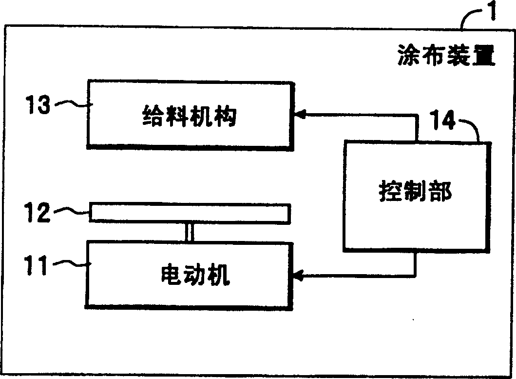
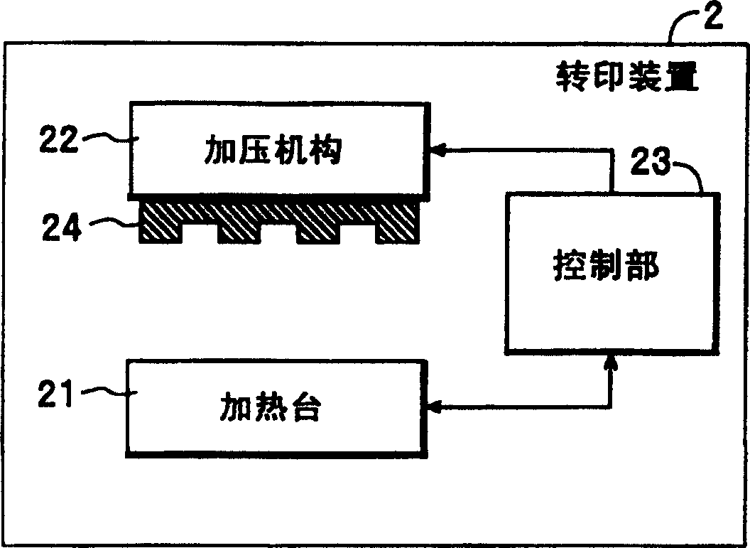
[0039] First, the configuration of the coating device 1 and the transfer device 2 will be described with reference to the drawings.

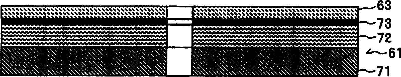
[0040] figure 1 The coating device 1 shown is that the resin material is coated on the disk-shaped base material 61 according to the concave-convex pattern forming method related to the present invention (refer to figure 2 ) to form a resin layer 63 on the surface (refer to figure 2 ) device is composed of a motor 11, a turntable 12, a feeding mechanism 13 and a control unit 14. The motor 11 rotates the turntable 12 according to a control signal of the control unit 14 . The structure of the turntable 12 is made to carry the disc-shaped base material 61 and is ro...


PUM


Abstract

A convex/concave pattern-forming stamp which is capable of making recesses of a convex/concave pattern uniform in depth and preventing deformation and peeling of portions of the convex/concave pattern at the same time. The stamp has on a surface thereof an annular area formed with protrusions for forming a convex/concave pattern in a resin layer on a surface of a disk-shaped substrate by being pressed against the resin layer. Protrusions for dispersing a pressure applied to the resin layer when the stamp is pressed against the resin layer are formed in at least one of an outer area located radially outward of the annular area and an inner area located radially inward of the annular area.

Description

technical field [0001] The present invention relates to a stamper for forming a concave-convex pattern that forms convex portions for forming a concave-convex pattern on a resin layer by pressing a predetermined annular region on the surface of a resin layer on the surface of a substrate, and an imprint mold for forming a concave-convex pattern using the stamper for forming a concave-convex pattern A concavo-convex pattern forming method for forming a concavo-convex pattern, and a magnetic recording medium in which data recording tracks are formed using the concavo-convex pattern formed by the concavo-convex pattern forming method. Background technique [0002] For example, in the process of manufacturing semiconductor elements or recording media, as a method of forming fine (nano-scale) concave-convex patterns on the resin layer on the surface of the base material, it has been proposed to form nano-scale concave-convex patterns on the imprint mold (mold). The imprint method...

Claims


Application Information

Patent Timeline
Patent Type & Authority Patents(China)
IPC IPC(8): G11B5/84B05D1/42C03C17/00G11B5/855
CPCC03C17/002B05D1/42G11B5/855
Inventor 藤田实高井充
Owner TDK CORPARATION
Why Eureka
Try Eureka