Shower door water retaining strip connector and shower door water retaining device

A technology of water retaining strips and connectors, applied in the field of sanitary ware, can solve the problems of time-consuming and laborious, hidden safety hazards, hidden dangers, etc., and achieve the effect of avoiding damage and saving manpower and material resources.

Active Publication Date: 2018-05-15
IDEAL SANITARY WARE CO LTD
View PDF3 Cites 1 Cited by
  • Summary
  • Abstract
  • Description
  • Claims
  • Application Information

AI Technical Summary

Problems solved by technology

This installation method makes it necessary to disassemble or move the glass door panel of the shower door when installing the water retaining strip, which is time-consuming and laborious, and there are certain safety hazards
In addition, the installed water retaining strip may interfere with the installation position between the installed water retaining strip and the glass plate of the shower door due to the error in marking the line, making the shower door unable to be installed normally
[0005] Moreover, since the water retaining strip is fixed in the installation groove by concrete or glue, when the water retaining strip is broken or damaged, it is troublesome to replace, and there may be a need to disassemble and reinstall the shower door, which is time-consuming and laborious. , there are also security risks
In addition, after the existing water-retaining strips are installed, the distribution shapes of the shower rooms are all in the more traditional right-angled or round-angled shape, which makes the installation shape of the shower room have great limitations. To design and install the shower room, the shower room has a single shape and structure, and it is difficult to maintain and replace the water retaining strip

Method used


Image

  • Shower door water retaining strip connector and shower door water retaining device
  • Shower door water retaining strip connector and shower door water retaining device
  • Shower door water retaining strip connector and shower door water retaining device

Examples


Embodiment Construction

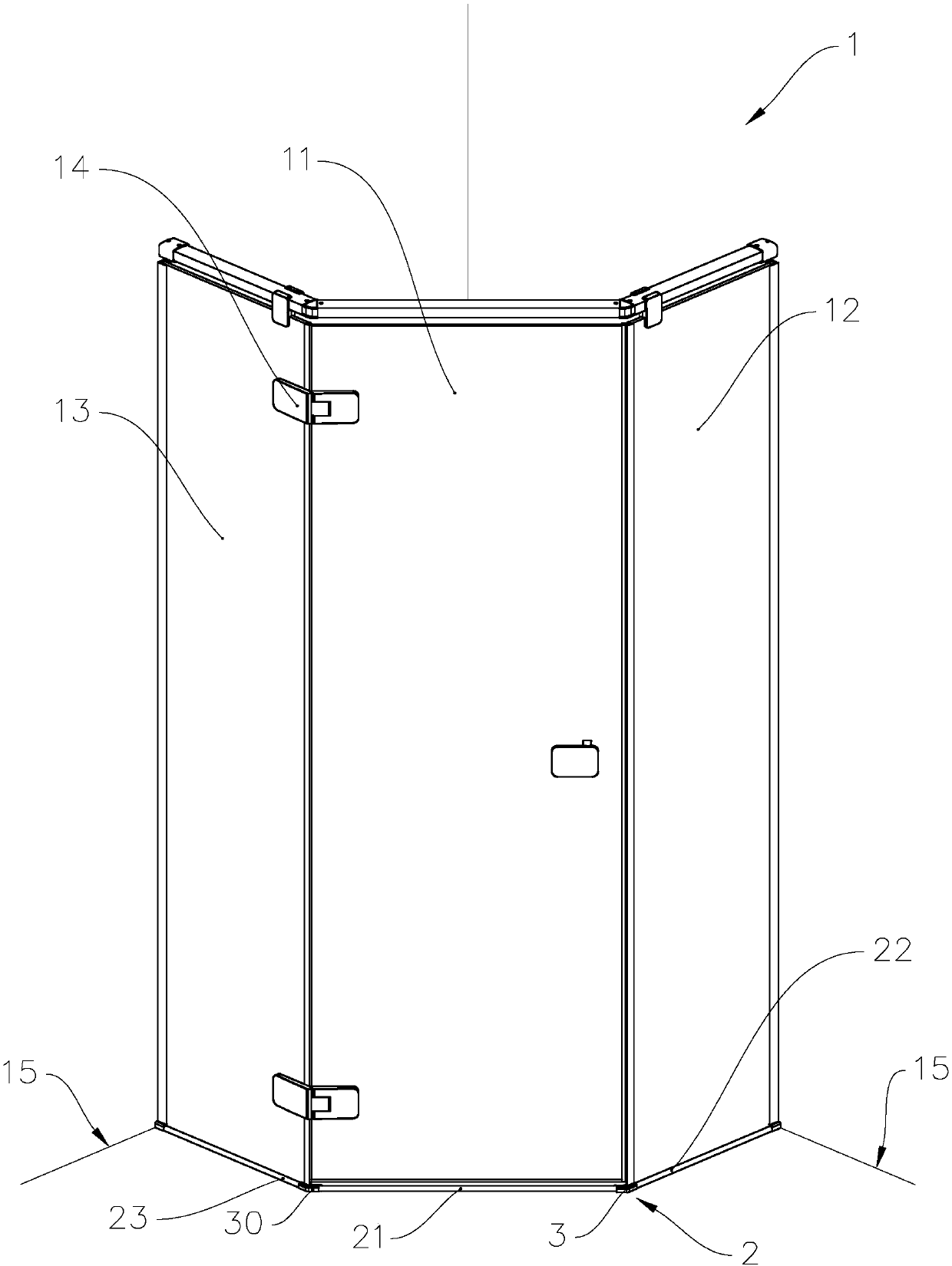
[0026] refer to figure 1 , figure 1 It is a schematic diagram of the installation position of the shower door water blocking device of the present invention. The shower door water retaining device 2 includes a first water retaining bar 21 , a second water retaining bar 22 , a third water retaining bar 23 , a first shower door water retaining bar connector 3 and a second shower door water retaining bar connector 30 . When installing the shower door, first fix the fixed frame on the wall 15, then connect the first fixed glass plate 12 and the second fixed glass plate 13 to the fixed frame installed on the wall 15, so that The first fixed glass plate 12 and the second fixed glass plate 13 are fixedly installed on the wall body 15 . Then, the movable glass plate 11 is connected with the fixed glass plate 11 through the hinge 14, so that the movable glass door 11 can rotate around the hinge axis of the hinge 14 relative to the second fixed glass plate 13 to form a hinged shower d...


PUM


Abstract

The invention provides a shower door water-retaining strip connector and a shower door water-retaining device. The shower door water-retaining strip connector comprises a connector body, wherein the connector body is provided with an installing portion and a connecting portion connected with the installing portion, the installing portion is provided with a through groove, the upper surface of the connecting portion is provided with a protrusion, the connecting portion is provided with a first end face and a second end face which are connected with a water-retaining strip, the first end face is provided with an installing groove, and an installing position is formed between the second end face and the third end face of the installing portion. The shower door water-retaining device is provided with the shower door water-retaining strip connector. The shower door water-retaining strip connector and the shower door water-retaining device have the advantages of being simple in structure, convenient to install and capable of achieving rapid water-retaining strip installation.

Description

technical field [0001] The invention relates to the technical field of sanitary appliances, in particular to a shower door water retaining bar connector and a water retaining device provided with the water retaining bar connector. Background technique [0002] Shower rooms are usually set in the toilet when people are decorating now, and present shower rooms usually use shower doors with glass plates. Most of the current shower doors are divided into two structures, namely sliding doors with tracks and hinge doors with hinges. [0003] Whether it is a shower door with a hinge door structure or a shower door with a sliding door structure, it is necessary to set a water retaining strip outside the glass plate to prevent the shower water from overflowing from the shower room during the shower process, causing the entire bathroom to be full of shower water. If there is too much water, it is easy to cause a safety hazard for the shower person to slip and fall. [0004] Existing...

Claims


Application Information

Patent Timeline
Patent Type & Authority Patents(China)
IPC IPC(8): E06B7/16
CPCE06B7/16
Inventor 危五祥
Owner IDEAL SANITARY WARE CO LTD
Why Eureka
Try Eureka