
Developing box

A developing cartridge and developing roller technology, applied in the field of developing cartridges, can solve the problems of reducing rotational torque, large rotational twisting force, shortening the service life of imaging equipment, etc.

Pending Publication Date: 2021-11-05
PRINT RITE UNICORN IMAGE PROD CO LTD
View PDF1 Cites 0 Cited by
  • Summary
  • Abstract
  • Description
  • Claims
  • Application Information

AI Technical Summary

Problems solved by technology

[0004] In order to solve the problem that when the driving head drives the developing roller, the powder feeding roller, and the stirring frame to rotate, the driving force receiving head receives a large rotational twisting force and a large torque, which easily damages the driving head in the imaging device, etc., the applicant published in CN110727186A The patent document of discloses a kind of development cartridge, transmits the rotational driving force by setting the transmission shaft, thereby reduces the torque of rotation, but, because in actual use, the toner accommodating part of the development cartridge is full of toner, so when the transmission shaft rotates When the driving force is transmitted, the outer peripheral wall of the transmission shaft will form friction with the stopper and the toner. During the rotation of the transmission shaft, the friction force needs to be overcome to generate torque. Therefore, the transmission head of the imaging device will still be subject to a large torque, which will Reduced lifespan of imaging equipment

Method used


Image

  • Developing box
  • Developing box
  • Developing box

Examples


Embodiment Construction

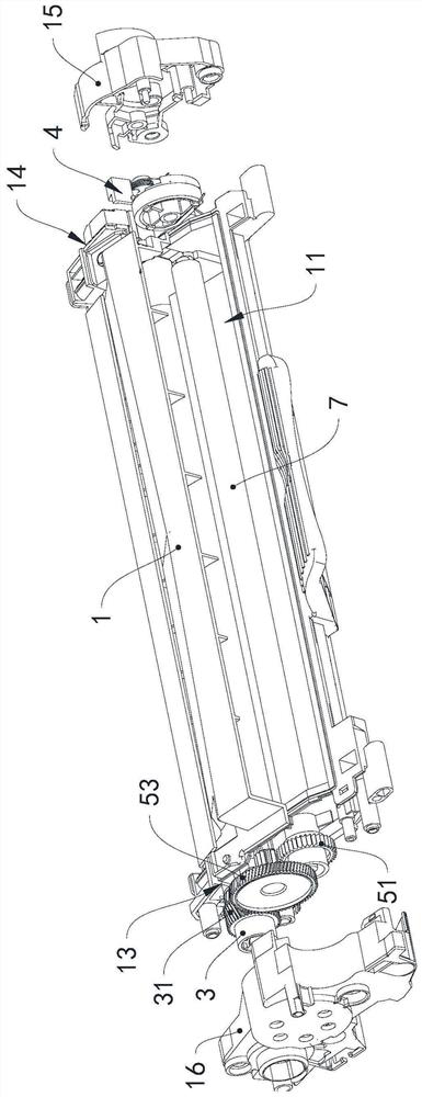
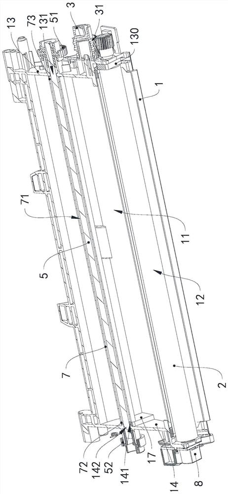
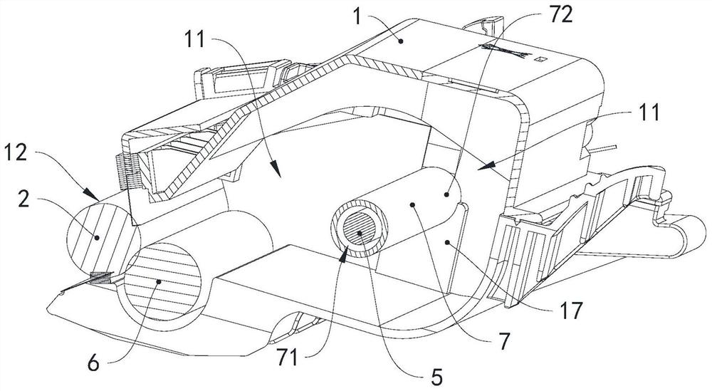
[0026] see Figure 1 to Figure 3 , The developing cartridge in this embodiment includes a box body 1, an end cover 15, an end cover 16, a developing roller 2, a powder feeding roller 6, a driving force receiving head 3, a detection mechanism 4, a transmission shaft 5, a sleeve 7 and conductive components 8.

[0027] The box body 1 has a toner container 11 and a powder outlet 12, the developing roller 2 is rotatably supported at the powder outlet 12, the axial end of the developing roller 2 is provided with a developing roller gear 21, and the powder feeding roller 6 is rotatably Supported in the toner container 11 and adjacent to the developing roller 2, the powder feeding roller 6 is used to transfer the toner in the toner container 11 to the developing roller 2, and the axial end of the powder feeding roller 6 is provided with a powder feeding roller. Roller gear 61.

[0028] The end cover 16 is installed on the first end wall 13, the driving force receiving head 3 is arra...


PUM


Abstract

The invention provides a developing box which comprises a box body, a developing roller, a driving force receiving head, a detection mechanism, a transmission shaft and a sleeve, the box body is provided with a carbon powder containing part and a powder outlet, the developing roller is rotatably supported at the powder outlet, the driving force receiving head is arranged on the first end wall of the box body, a tooth part is arranged on the peripheral wall of the driving force receiving head, the detection mechanism is arranged on the second end wall of the box body, the transmission shaft is columnar and extends in the length direction of the box body, the transmission shaft is rotatably installed in the carbon powder containing part, a first end of the transmission shaft is provided with a first driving wheel, the first driving wheel and the driving force receiving head are located on the same side of the box body, and the first driving wheel is in transmission connection with the driving force receiving head. The second end of the transmission shaft is provided with a second driving wheel which is matched with the rotating piece. A mounting cavity isolated from the carbon powder containing part is formed in the sleeve, and the transmission shaft is located in the mounting cavity and is in clearance fit with the sleeve. The developing box can reduce the torque generated by rotation.

Description

technical field [0001] The invention relates to the field of electrophotographic imaging, in particular to a developing box. Background technique [0002] Imaging equipment usually uses a detachable developing cartridge to provide toner to develop the electrostatic latent image on the photosensitive member, and then transfer it to a medium such as paper to form a visible image. [0003] An existing developing cartridge includes a box body, the two axial ends of the box body are respectively provided with a drive head and a detection wheel with missing teeth, the box body has a developer storage chamber and a powder outlet for accommodating the developer, and the developer storage chamber There is a stirring frame for stirring the developer inside, the developing roller is set at the powder outlet, the gear train driving the stirring frame and the developing roller to rotate is installed outside the box body, the first axial end of the stirring frame is provided with a first ...

Claims


Application Information

Patent Timeline
Patent Type & Authority Applications(China)
IPC IPC(8): G03G15/08G03G21/18
CPCG03G15/0891G03G21/186
Inventor 杨晓锋苏健强易新华
Owner PRINT RITE UNICORN IMAGE PROD CO LTD
Learn More