Detachable loop heat pipe

A loop heat pipe and adiabatic section technology, applied in indirect heat exchangers, heat exchange equipment, heat exchanger shells, etc., can solve the problem that the loop heat pipe cannot be changed in time, cannot meet the changing needs, and the pipeline length of the loop heat pipe is long. and other problems, to achieve the effect of simple structure, cost saving and reduction of flow resistance

Active Publication Date: 2022-07-01
ZHONGBEI UNIV
View PDF8 Cites 0 Cited by
  • Summary
  • Abstract
  • Description
  • Claims
  • Application Information

AI Technical Summary

Problems solved by technology

[0005] Current loop heat pipes generally have a fixed structure and a fixed length. When the distance between the evaporation section and the condensation section of the loop heat pipe is too long, the loop heat pipe pipeline that needs to be prepared is relatively long, which makes manufacturing difficult, and because the overall length is Fixed, resulting in that the loop heat pipe cannot be changed in time when the demand changes, and cannot meet the changing needs

Method used


Image

  • Detachable loop heat pipe
  • Detachable loop heat pipe
  • Detachable loop heat pipe

Examples


Embodiment Construction

[0027] The specific embodiments of the present invention will be described in detail below with reference to the accompanying drawings.

[0028] In this article, if there are no special instructions, when it comes to formulas, " / " means division, and "×" and "*" mean multiplication.

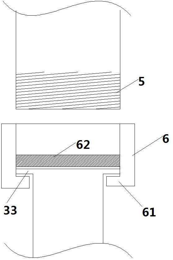
[0029] The upper and lower parts of the description of the present application refer to the direction of the evaporation section or the condensation section as the top, and the direction of the adiabatic section to the bottom. E.g, figure 2 The evaporation section or condensation section in the upper part is the upper part, and the adiabatic part is in the lower part, which is the lower part.

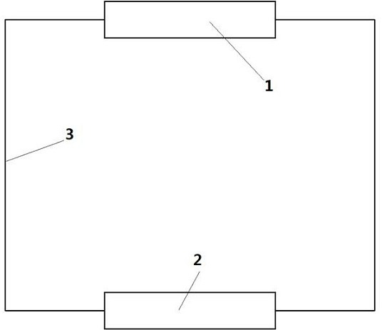
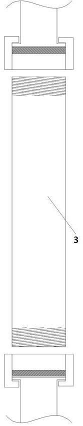
[0030] Figure 1-4 A loop heat pipe is disclosed. like figure 1 A loop heat pipe is shown, including an evaporation section 1, a condensation section 2 and an adiabatic section 3. The insulation section includes a steam insulation section 31 and a liquid insulation section 32. The fluid absorbs heat a...


PUM


Abstract

The invention provides a detachable loop heat pipe which comprises an evaporation section, a condensation section and a heat insulation section, the heat insulation section comprises a steam heat insulation section and a liquid heat insulation section, fluid absorbs heat and evaporates in the evaporation section, enters the condensation section through the steam heat insulation section and then enters the evaporation section through the liquid heat insulation section after releasing heat in the condensation section, and the liquid heat insulation section is communicated with the liquid heat insulation section. The evaporation section, the condensation section and the heat insulation section are mutually independent parts, two end parts of the evaporation section are respectively connected with one end of the steam heat insulation section and one end of the liquid heat insulation section through detachable parts, and two end parts of the condensation section are respectively connected with the other end of the steam heat insulation section and the other end of the liquid heat insulation section through detachable parts. Therefore, the evaporation section, the condensation section and the heat insulation section form a loop heat pipe. According to the loop heat pipe, an existing loop heat pipe is improved, the detachable components are arranged to be connected with the evaporation section, the condensation section and the heat insulation section, so that all the components are rapidly detached and replaced, the requirements of different heat exchange occasions are met, the system structure is simple, and the cost is saved.

Description

technical field [0001] The invention relates to a heat pipe technology, in particular to a detachable loop heat pipe, which belongs to the field of heat pipes of F28D15 / 02. Background technique [0002] Heat pipe technology is a heat transfer element called "heat pipe" invented by George Grover of Los Alamos National Laboratory in the United States in 1963. It makes full use of the principle of heat conduction and phase change medium. The rapid heat transfer property of the heat pipe, the heat of the heating object is quickly transferred to the outside of the heat source through the heat pipe, and its thermal conductivity exceeds that of any known metal. [0003] The loop heat pipe is a high-efficiency two-phase heat transfer equipment, which has the characteristics of high heat transfer performance, long-distance heat transfer, excellent temperature control characteristics, arbitrary bending of the pipeline, and convenient installation. Compared with the advantages, the lo...

Claims


Application Information

Patent Timeline
Patent Type & Authority Applications(China)
IPC IPC(8): F28D15/02F28D15/04F28F9/26
CPCF28D15/0266F28D15/04F28F9/26F28F2275/20
Inventor 常建龙许俊杰贺柳景高飞刘彦臣潘玉田郭保全
Owner ZHONGBEI UNIV
Why Eureka
Try Eureka