Ultrasonic nondestructive testing device for shaft parts

A non-destructive testing, ultrasonic technology, applied in measuring devices, using sound waves/ultrasonic waves/infrasonic waves to analyze solids, using sound waves/ultrasonic waves/infrasonic waves for material analysis, etc., can solve problems such as inconvenient operation, prone to failure, high operating requirements, etc., to achieve Reduce the impact of smoothness, improve the production process, and reduce the effect of work intensity

Pending Publication Date: 2020-07-10
南通银河测控技术开发有限公司
View PDF2 Cites 2 Cited by
  • Summary
  • Abstract
  • Description
  • Claims
  • Application Information

AI Technical Summary

Problems solved by technology

The traditional ultrasonic non-destructive testing method usually uses hand-held flaw detection equipment to manually select points and scan on the parts to be tested. The detection efficiency is low and the labor cost is high, especially for some parts with large batch processing quantities. It is difficult to meet the needs of efficient production operations by using manual hand-held equipment for inspection and flaw detection
[0003] At present, some automatic testing equipment has also appeared in the field of non-destructive testing of shaft parts, but there are deficiencies such as complex structure, inconvenient operation, and high requirements for surface processing accuracy of the parts to be tested.
For example, the publication number is CN103217477, an axle radial automatic flaw detection device. The axle to be inspected is

Method used


Image

  • Ultrasonic nondestructive testing device for shaft parts
  • Ultrasonic nondestructive testing device for shaft parts
  • Ultrasonic nondestructive testing device for shaft parts

Examples


Embodiment Construction

[0030] In order to better understand the present invention, a more clear and complete description will be made below in conjunction with the accompanying drawings and specific embodiments. The listed embodiments are preferred forms of the present invention, rather than all embodiments. Based on the embodiments of the present invention, all other embodiments obtained by those of ordinary skill in the art without creative work belong to The protection scope of the present invention.

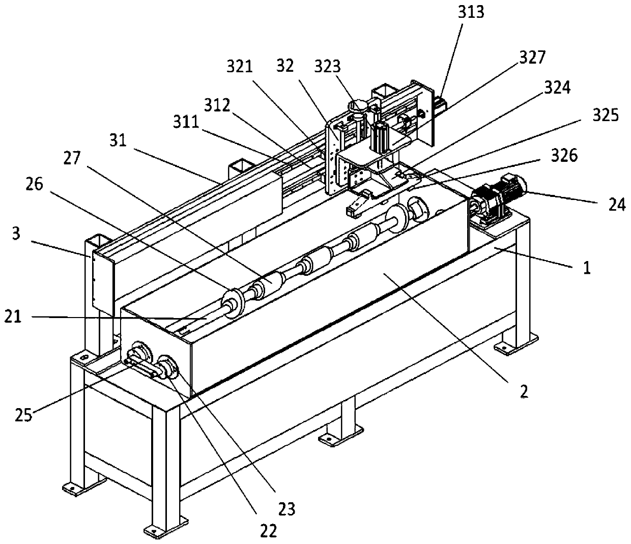
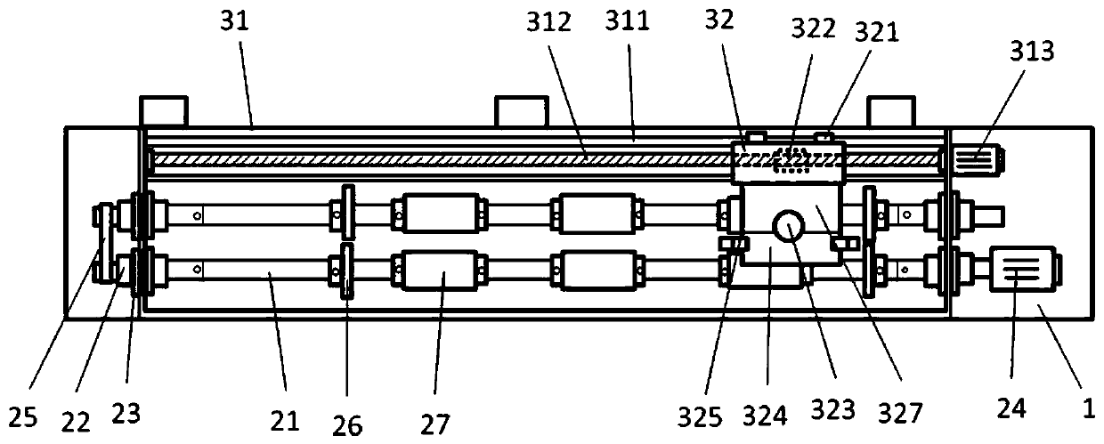
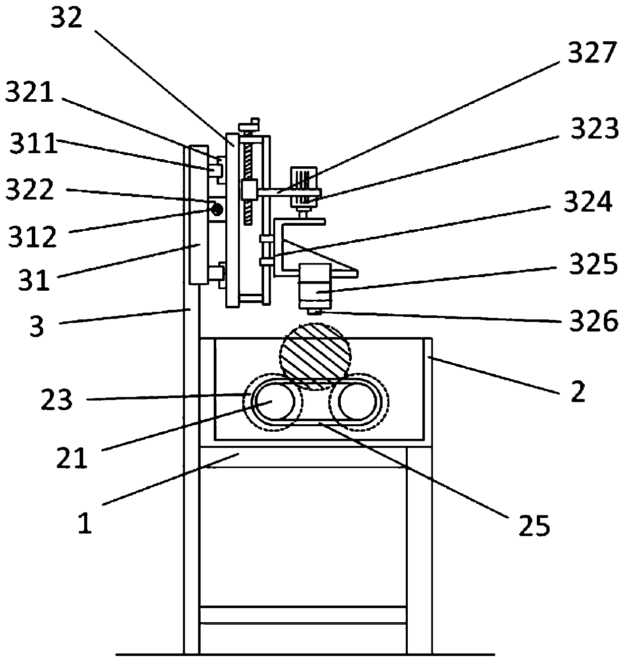
[0031] An ultrasonic non-destructive testing device for shaft parts, refer to Figure 1 to Figure 3 As shown, it includes a detection workbench 1 and a controller 4. The detection workbench 1 is provided with a coupling water tank 2 and a cantilever beam unit 3, and a pair of rollers parallel to each other and with the same diameter are arranged horizontally in the coupling water tank 2. 21. The rollers 21 are all set on the wall of the coupling water tank 2, and the connection between the rollers...


PUM


Abstract

The invention provides an ultrasonic nondestructive testing device for shaft parts. The device comprises a detection workbench and a controller. The detection workbench is provided with a coupling water tank and a cantilever beam unit. A pair of parallel rolling shafts with the same diameter are arranged in the coupling water tank in the horizontal direction, the two ends of each rolling shaft arearranged on the tank wall of the coupling water tank in a penetrating mode through bearings and sealing sleeves, a synchronous belt is connected between the rolling shafts, and the rolling shafts aredriven by a gear motor arranged outside the coupling water tank to rotate in the axial direction. The cantilever beam unit comprises a cross beam arranged above the water tank and parallel to the driving rolling shaft, a probe lifting base capable of moving horizontally is arranged on the cross beam, a probe frame capable of moving up and down is arranged on the probe lifting base, and a plurality of ultrasonic probes are arranged on the probe frame. The flaw detection device is simple in structure, convenient to operate, low in requirement for surface smoothness of a to-be-detected part, notprone to abrasion of the probe, convenient to disassemble, assemble and replace due to the modular design of the probe set and suitable for nondestructive detection application of the shaft parts ofvarious specifications.

Description

technical field [0001] The invention belongs to the technical field of nondestructive testing equipment, and in particular relates to an ultrasonic nondestructive testing device for shaft parts. Background technique [0002] When shaft parts are applied to equipment and workpieces, they usually need to bear large loads and torques. If they have processing defects such as cracks and internal shrinkage holes, they are prone to deformation or broken shafts during use, causing equipment damage. Damage or cause safety accidents, therefore, most shaft parts require non-destructive testing in the process of processing. At present, the more commonly used detection method is ultrasonic detection, which uses the difference in the acoustic properties of materials and their defects to detect the ultrasonic wave propagation and energy changes during reflection and penetration to detect internal defects in materials. The traditional ultrasonic non-destructive testing method usually uses ...

Claims


Application Information

Patent Timeline
IPC IPC(8): G01N29/04G01N29/22G01N29/265G01N29/28
CPCG01N29/04G01N29/22G01N29/265G01N29/28G01N2291/0234G01N2291/106
Inventor 达刚季建华姜振祥王英锋
Owner 南通银河测控技术开发有限公司
Why Eureka
Try Eureka