Heat source tower liquid distribution device with variable flow self-adaptive function

An adaptive, heat source tower technology, applied in the field of heat source towers, can solve the problems of fixed design flow, simple structure, cumbersome disassembly and replacement, etc., and achieve the effect that the uniformity of liquid distribution is basically unchanged, the replacement is simple and easy, and the overall structure is simple

Active Publication Date: 2017-02-22
SOUTHEAST UNIV
View PDF7 Cites 0 Cited by
  • Summary
  • Abstract
  • Description
  • Claims
  • Application Information

AI Technical Summary

Problems solved by technology

For the heat source tower heat pump system that operates in both winter and summer, the installation of the nozzle is fixed and not replaced. During the operation, when the flow rate decreases, the liquid level in the tank will also decrease, so that the spraying distance of the liquid distribution nozzle becomes shorter, and the overall Decreased liquid distribution uniformity
In addition, the nozzles currently used on heat source towers have a simple structure, large loss of water falling speed, uneven spraying, and fixed design flow, which makes it difficult to adapt to the needs of different flow rates in winter and summer of heat source towers and variable flow operation under different working conditions
[0005] Therefore, how to ensure that the heat source tower has a good liquid distribution effect under different solution flow rates, so as to ensure the heat exchange effect of the heat source tower in winter and summer, and at the same time avoid the disadvantages of cumbersome disassembly, large speed loss, and easy blockage, etc., to design a A heat source tabby liquid device that can adapt to different flow conditions has become an urgent technical problem for those skilled in the art

Method used


Image

  • Heat source tower liquid distribution device with variable flow self-adaptive function
  • Heat source tower liquid distribution device with variable flow self-adaptive function
  • Heat source tower liquid distribution device with variable flow self-adaptive function

Examples


Embodiment Construction

[0022] The present invention will be further described below in conjunction with the specific embodiments and the accompanying drawings.

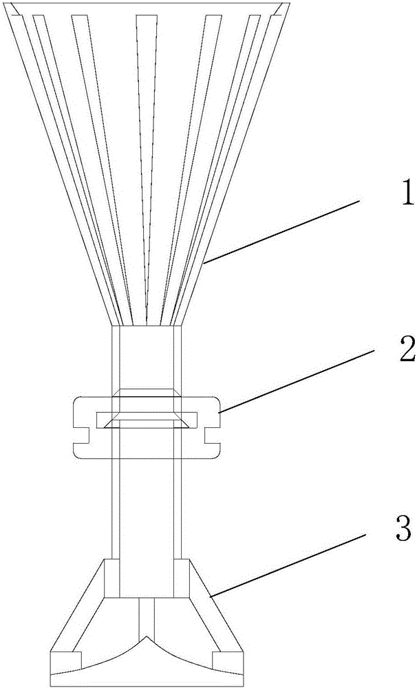
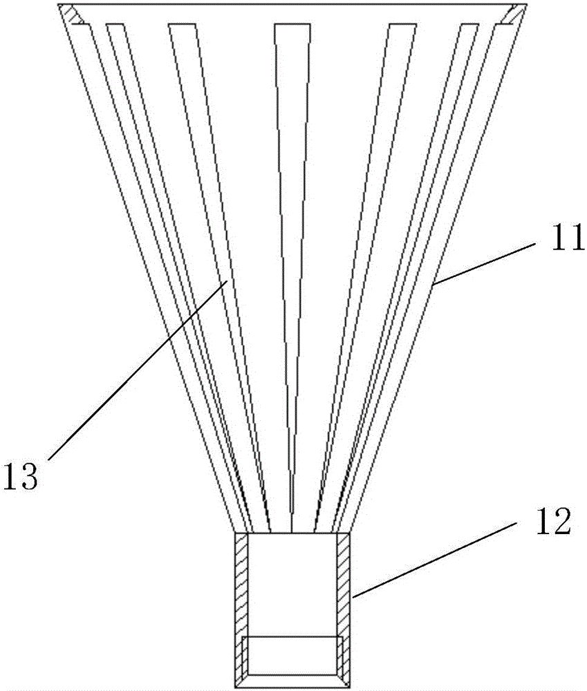
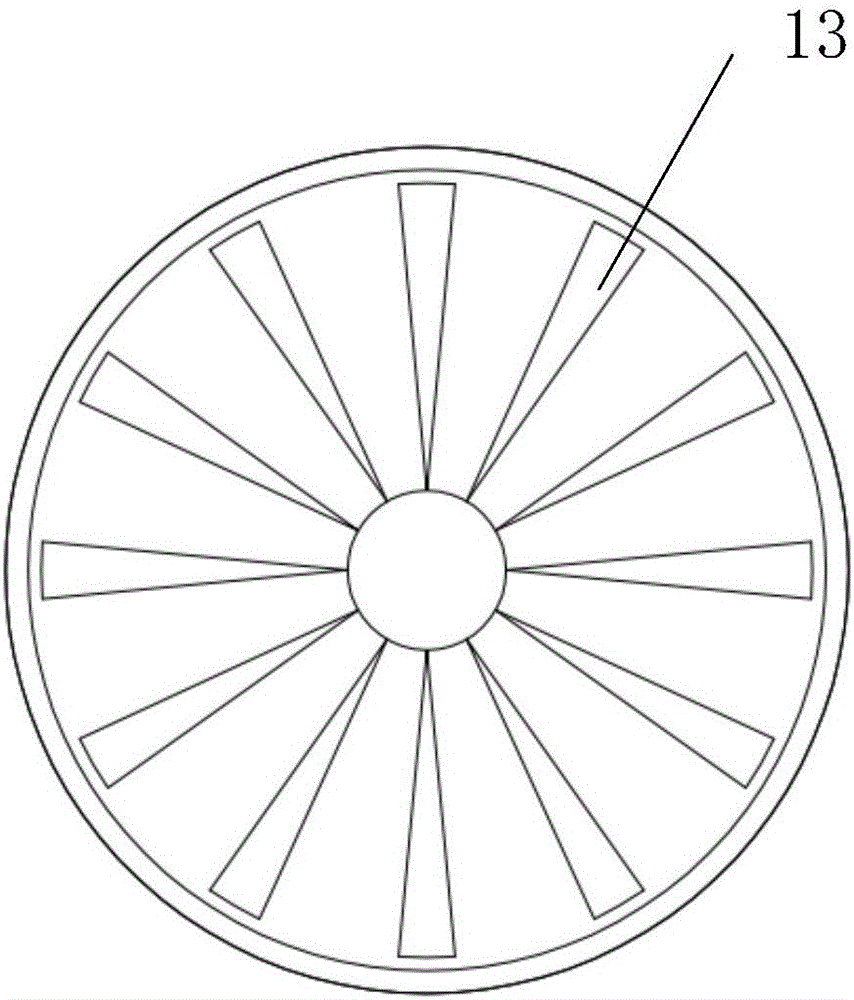
[0023] The heat source tabby liquid device with variable flow self-adaptive function of the present invention includes three parts: a funnel 1 , an apron 2 and a nozzle 3 . The funnel 1 includes a bucket body 11 and a lower tube 12, and an internal thread is arranged inside the lower tube 12; an annular groove 21 is arranged inside the apron 2, and an annular groove 22 is arranged outside; the nozzle 3 includes a splash tube 31, a support frame 32, and a splash plate 33. The splash tube 31 is provided with external threads and shoulders, the top of the support frame 32 is connected with the splash tube 31, and the bottom end is connected with the splash plate 33; the funnel 1 and the nozzle 3 are fixed by threaded connection, the apron 2 and the nozzle 3. Fix by inserting the card shoulder into the annular groove. The bucket body 11 of the...


PUM


Abstract

The invention discloses a heat source tower liquid distribution device with a variable flow self-adaptive function. The heat source tower liquid distribution device with the variable flow self-adaptive function comprises a funnel, a spraying head which is connected with the lower part of the funnel and a rubber ring which is mounted on the spraying head; the funnel comprises a funnel body and a lower pipe which is connected and mounted at the lower part of the funnel pipe; the spraying head comprises a splashing pipe, a supporting frame, and a liquid splashing disc which are connected in sequence from top to bottom; clamping shoulders are arranged on the outer wall of the splashing pipe; an annular groove is formed in the rubber ring; and the clamping shoulders are embedded into the annular groove so that the rubber ring is fixedly mounted on the spraying head. The heat source tower liquid distribution device with the variable flow self-adaptive function can adapt to different flows, ensures a normal liquid level, solves the problems that the flow is reduced and the liquid distribution uniformity is reduced in working conditions, has the variable flow self-adaptive function, and also has the advantages of simple structure, convenience in detachment and replacement and the like.

Description

technical field [0001] The invention belongs to the technical field of heat source towers, and relates to a heat source tower cloth liquid device with a variable flow self-adaptive function. Background technique [0002] The heat source tower heat pump system is a new type of cold and heat source scheme for buildings. During the heating operation in winter, the solution exchanges heat with the air in the heat source tower, absorbing the heat in the air as the low-level heat source of the heat pump to realize heating; in summer, cooling At this time, the heat source tower is used as a cooling tower, and the water in the tower exchanges heat with the air to discharge the indoor heat to the outside. Due to the difference in the amount of heat exchange in the tower in winter and summer, the form of heat exchange is also different, and the flow in the heat source tower in winter and summer is also very different. [0003] At the same time, the load of the heat source tower in ...

Claims


Application Information

Patent Timeline
Patent Type & Authority Applications(China)
IPC IPC(8): F28F25/06F25B30/06F28F25/02F28C1/00
CPCF25B30/06F28C1/00F28F25/02F28F25/06
Inventor 梁彩华陈睿张小松
Owner SOUTHEAST UNIV
Why Eureka
Try Eureka