Optical fiber loop framework capable of reducing polarization error of optical fiber gyroscope and method for winding optical fiber loop thereon

A technology of fiber optic ring skeleton and fiber optic gyroscope, which is applied in the direction of Sagnac effect gyroscopes, measuring devices, instruments, etc., can solve problems affecting the measurement accuracy of fiber optic gyroscope angle sensing, intensity-type polarization errors, etc., and reduce polarization Effects of cross-coupling, reducing polarization errors, and reducing influence

Inactive Publication Date: 2017-02-22
武汉长盈通光电技术股份有限公司
View PDF6 Cites 15 Cited by
  • Summary
  • Abstract
  • Description
  • Claims
  • Application Information

AI Technical Summary

Problems solved by technology

As the number of fiber ring layers increases, the stress on the fiber will increase, causing polarization cross-coupling, resulting in intensity-type polarization errors, and affecting the measurement accuracy of the fiber optic gyroscope angle sensor.

Method used


Image

  • Optical fiber loop framework capable of reducing polarization error of optical fiber gyroscope and method for winding optical fiber loop thereon
  • Optical fiber loop framework capable of reducing polarization error of optical fiber gyroscope and method for winding optical fiber loop thereon
  • Optical fiber loop framework capable of reducing polarization error of optical fiber gyroscope and method for winding optical fiber loop thereon

Examples


Embodiment Construction

[0030] Below in conjunction with accompanying drawing, specific embodiment of the present invention is described in further detail:

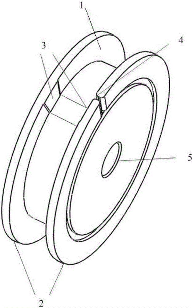
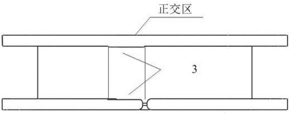
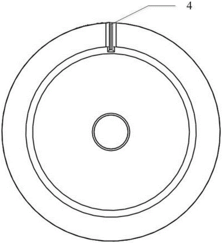
[0031] like Figure 1 ~ Figure 3 As shown, the optical fiber ring skeleton for reducing the polarization error of the fiber optic gyroscope provided by the present invention includes an insulating skeleton body 1, and a pair of concave and convex positioning grooves 3 with opposite concave and convex are arranged on the inner side of the side wall 2 of the skeleton body 1 along the radial direction, and the positioning grooves 3 are In the fan-shaped area with an angle of 10°, the depth of the positioning groove 3 is the same as the diameter of the optical fiber; the left side wall 2 of the skeleton body 1 is provided with a fiber outlet groove 4, and the width of the fiber outlet groove 4 is the same as the diameter of the optical fiber.

[0032] In order to facilitate the winding and curing of the optical fiber ring, an assembly hole 5 is prov...


PUM


Abstract

The invention discloses an optical fiber loop framework capable of reducing a polarization error of an optical fiber gyroscope. The optical fiber loop framework comprises an insulated framework body, wherein a pair of positioning slots with opposite concave and convex directions is radially formed in the inner sides of the side walls of the framework body; the positioning slots are fan-shaped zones with the angles of (10 +/- 2) degrees; the depths of the positioning slots are equal to the diameter of an optical fiber; an optical fiber outlet slot is formed in one side wall of the framework body; the width of the optical fiber outlet slot is equal to the diameter of the optical fiber. A method for winding an optical fiber loop on the optical fiber loop framework comprises the following steps: 1) preparing the optical fiber with sufficient length, keeping a sufficient tail fiber, and marking two end points and a middle point of the optical fiber according to the length of the optical fiber; 2) preparing the optical fiber which can be wound into about two layers, and winding a bottom layer by an orthogonal winding method; 3) tightly adhering the optical fiber to the inner side of the right wall of the framework body, and winding the optical fiber by the orthogonal winding method till the respective end points; 4) fixing the tail fiber to the framework body; 5) performing post-curing treatment. The following beneficial effects are achieved: polarization cross coupling is effectively reduced, the polarization error is reduced, and the symmetry is better.

Description

technical field [0001] The invention relates to the field of optical fiber rings for optical fiber gyroscopes, in particular to an optical fiber ring framework for reducing polarization errors of optical fiber gyroscopes and a method for winding optical fiber rings. Background technique [0002] Polarization error suppression of FOG is one of the key technologies in the development of FOG. The original fiber optic gyroscope uses single-mode fiber to wind the fiber coil. Due to the linear birefringence caused by the ellipticity of the core of the single-mode fiber and the stress generated during bending, twisting, and winding, the single-mode fiber coil cannot maintain the line of the input light wave. Polarization state, when returning to the interference point, the polarization state of the light wave is uncertain, which will cause the output signal of the fiber optic gyroscope to decline, or even lose the gyroscope effect. For this reason, fiber optic gyroscopes are gener...

Claims


Application Information

Patent Timeline
Patent Type & Authority Applications(China)
IPC IPC(8): G01C19/64G01C25/00
CPCG01C19/64G01C25/00
Inventor 万琼何元兵冯琦
Owner 武汉长盈通光电技术股份有限公司
Why Eureka
Try Eureka