
A preparation method of mixed polarization fiber optic gyroscope optical path and depolarizer

A technology of fiber optic gyroscope and depolarizer, which is applied in Sagnac effect gyroscopes, instruments, measuring devices, etc., can solve the problems that only low polarization light sources are applicable, and gyroscopes are easily affected by light source performance fluctuations, and achieve guaranteed power Stability and wavelength stability, improve the effect of depolarization, improve the effect of zero bias stability and scale factor stability

Active Publication Date: 2017-03-01
HUBEI SANJIANG AEROSPACE HONGFENG CONTROL
View PDF9 Cites 0 Cited by
  • Summary
  • Abstract
  • Description
  • Claims
  • Application Information

AI Technical Summary

Problems solved by technology

However, the gyroscope with this optical path structure is easily affected by the fluctuation of light source performance, and is only suitable for low polarization light source

Method used

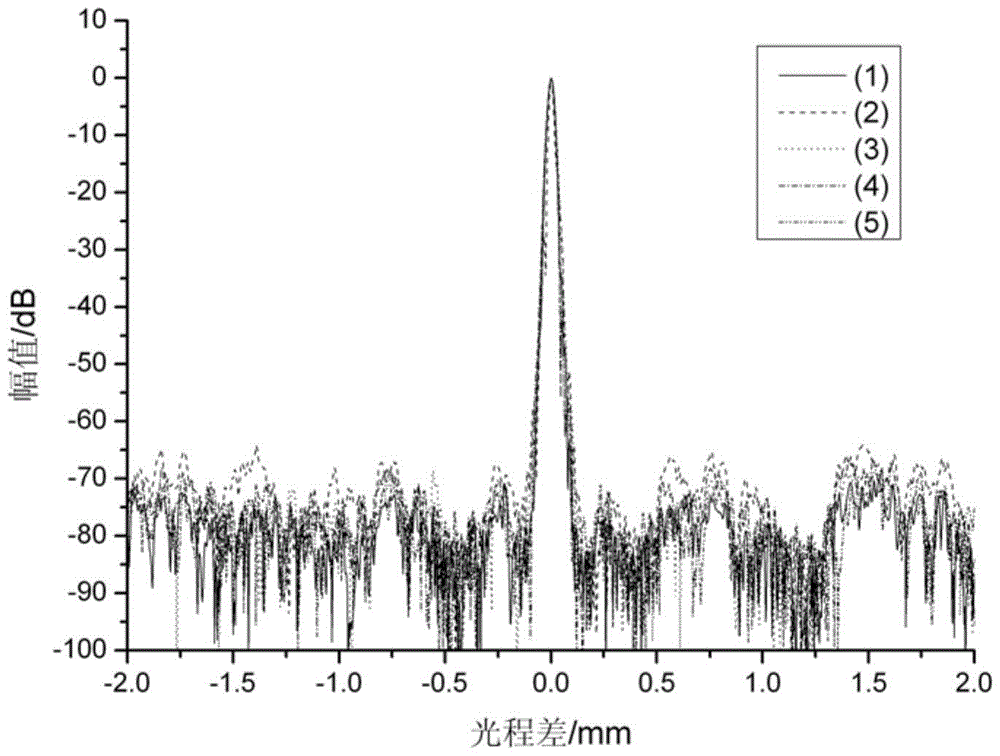

Image

  • A preparation method of mixed polarization fiber optic gyroscope optical path and depolarizer
  • A preparation method of mixed polarization fiber optic gyroscope optical path and depolarizer
  • A preparation method of mixed polarization fiber optic gyroscope optical path and depolarizer

Examples


Embodiment Construction

[0028] In order to make the object, technical solution and advantages of the present invention clearer, the present invention will be further described in detail below in conjunction with the accompanying drawings and embodiments. It should be understood that the specific embodiments described here are only used to explain the present invention, not to limit the present invention.

[0029] In the polarization mixing gyro optical path proposed by the present invention, the Y waveguide input tail fiber adopts the polarization maintaining optical fiber, and the Y waveguide is preceded by a depolarizer, and the depolarizer is made of the Y waveguide input tail fiber. It reduces the requirements of the polarization degree of the light source for the mixed-polarization gyro optical path, and is not only suitable for low-polarization wide-spectrum light sources, but also can ensure the power stability and wavelength stability of the Y-waveguide polarization signal through the depolari...


PUM


Abstract

The invention discloses a mixed polarized fiber-optic gyroscope light path and a preparation method of a depolarizer of the mixed polarized fiber-optic gyroscope light path. The mixed polarized fiber-optic gyroscope light path comprises a single-mode fiber coupler, a broad-band light source, a depolarizer, a Y waveguide, a polarization-maintaining fiber ring and a detector, wherein the broad-band light source is welded with the first end of the single-mode fiber coupler; the tail fiber of the broad-band light source is a single-mode fiber; the input end of the depolarizer is welded with the second end of the single-mode fiber coupler; the Y waveguide is in shaft coupling with the output end of the depolarizer; the polarization-maintaining fiber ring is welded with the Y waveguide; the detector is welded with the third end of the single-mode fiber coupler; the tail fiber of the detector is the single-mode fiber; the depolarizer is formed by two sections of polarization-maintaining fibers, of which the length ratio is 1 to 2; the lengths of the polarization-maintaining fibers are respectively L1 and L2; L1 is greater than or equal to (LD+L3)*1.3; L2 is greater than or equal to (LD+L3)*1.3, L2-L1 is greater than or equal to (LD+L3)*1.3; and the depolarizer is fabricated by a polarization-maintaining input tail fiber of the Y waveguide. The design of the depolarizer is considered from two aspects of device-level depolarization and avoidance of optical path delay compensation between wave trains generated in subsequent light paths; the demands of the mixed polarized light path on the light source polarization degree are lowered; and the polarization error in the gyroscope light path is reduced.

Description

technical field [0001] The invention belongs to the field of fiber optic gyroscopes, and more specifically relates to a preparation method of a mixed-polarization fiber optic gyroscope optical path and a depolarizer. Background technique [0002] The fiber optic gyroscope is an inertial instrument based on the Sagnac effect. Because of its small size, light weight, wide range of precision, and no moving parts, it has been widely used in various fields such as land, sea, air, and space. As the sensitive and detection part of the Sagnac effect, the gyro optical path is the core component of the fiber optic gyro. The mixed polarization optical path is a form of optical path of the fiber optic gyroscope. In the mixed polarization optical path, some optical devices use polarization-maintaining devices, such as polarization-maintaining fiber rings, and some devices use single-mode devices, such as fiber couplers. [0003] In 2006, Wang Wei, Yang Qingsheng and others of China Ae...

Claims


Application Information

Patent Timeline
Patent Type & Authority Patents(China)
IPC IPC(8): G01C19/72G01C25/00
CPCG01C19/72G01C25/00
Inventor 王学勤
Owner HUBEI SANJIANG AEROSPACE HONGFENG CONTROL
Learn More