A polarization-maintaining photonic crystal fiber optic gyroscope and its manufacturing method

A photonic crystal fiber and polarization-maintaining fiber technology is applied in Sagnac effect gyroscopes, measuring devices, instruments, etc., to achieve the effects of reducing optical power loss, reducing polarization error, and improving zero-bias stability

Active Publication Date: 2018-05-22
HUBEI SANJIANG AEROSPACE HONGFENG CONTROL
View PDF7 Cites 0 Cited by
  • Summary
  • Abstract
  • Description
  • Claims
  • Application Information

AI Technical Summary

Problems solved by technology

[0006] Aiming at the problem of the bias stability of the fiber optic gyroscope in the prior art, the present invention provides a polarization-maintaining photonic crystal fiber optic gyroscope, the purpose of which is to improve the bias stability of the fiber optic gyroscope and give full play to the advantages of the photonic crystal fiber optic gyroscope, thereby solving the problem of above technical issues

Method used


Image

  • A polarization-maintaining photonic crystal fiber optic gyroscope and its manufacturing method
  • A polarization-maintaining photonic crystal fiber optic gyroscope and its manufacturing method
  • A polarization-maintaining photonic crystal fiber optic gyroscope and its manufacturing method

Examples


Embodiment Construction

[0022] In order to make the object, technical solution and advantages of the present invention clearer, the present invention will be further described in detail below in conjunction with the accompanying drawings and embodiments. It should be understood that the specific embodiments described here are only used to explain the present invention, not to limit the present invention. In addition, the technical features involved in the various embodiments of the present invention described below can be combined with each other as long as they do not constitute a conflict with each other.

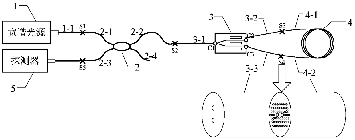
[0023] Such as figure 1 As shown, a polarization-maintaining photonic crystal fiber optic gyroscope optical path includes a polarization-maintaining fiber coupler 2, a wide-spectrum light source 1 that is fused with the first end (2-1) of the polarization-maintaining fiber coupler and whose pigtail is a polarization-maintaining fiber. The Y waveguide 3 fused with the polarization-maintaining pi...


PUM


Abstract

The invention discloses a polarization-maintaining photonic crystal fiber gyroscope light path. The polarization-maintaining photonic crystal fiber gyroscope light path comprises a polarization-maintaining fiber coupler, a broad band optical source, a Y waveguide, a polarization-maintaining photonic crystal fiber ring spliced with a Y waveguide output tail fiber and a detector and is characterized in that the polarization-maintaining fiber coupler acts on a polarization-maintaining fiber fast axis, a Y waveguide tail fiber is a stress birefringence polarization-maintaining fiber, 0-degree axis alignment splicing is performed between the fiber fast axis and the Y waveguide TE mode, the polarization-maintaining pohotonic crystal fiber ring is obtained by winding double macropore type polarization-maintaining photonic crystal fibers, 90-degree axis alignment splicing is performed between the axial direction of double macropore type polarization-maintaining photonic crystal fibers and the axial direction of the stress birefringence polarization-maintaining fiber, and useful signals in the gyroscope light path are all transmitted in the fast axis. The photonic crystal fiber gyroscope light path has the advantages of low temperature sensitiveness, radiation resistance and the like of a common photonic crystal fiber gyroscope, further effectively inhibits polarization errors of the gyroscope and facilitates improvement of zero-bias stability of the fiber gyroscope.

Description

technical field [0001] The invention belongs to the field of fiber optic gyroscopes, and more specifically relates to a fiber optic gyroscope optical path using a polarization-maintaining photonic crystal fiber as a sensitive ring. Background technique [0002] The fiber optic gyroscope is an inertial instrument based on the Sagnac effect. Because of its small size, light weight, wide range of precision, and no moving parts, it has been widely used in various fields such as land, sea, air, and space. As the sensitive and detection part of the Sagnac effect, the gyro optical path is the core component of the fiber optic gyro. [0003] Due to the special advantages of good radiation resistance, high temperature stability, and good bending performance, photonic crystal fibers have great application potential in the optical path of fiber optic gyroscopes. In particular, the use of photonic crystal fiber to wind the fiber ring is beneficial to improve the temperature stability ...

Claims


Application Information

Patent Timeline
Patent Type & Authority Patents(China)
IPC IPC(8): G01C19/72G01C25/00
CPCG01C19/72G01C25/005
Inventor 王学勤彭志强李亮郭礼芹
Owner HUBEI SANJIANG AEROSPACE HONGFENG CONTROL
Why Eureka
Try Eureka