Eureka AIR delivers breakthrough ideas for toughest innovation challenges, trusted by R&D personnel around the world.

Fiber-optic gyroscope temperature control structure and method for using same

A temperature control method and fiber optic gyroscope technology, applied in the direction of temperature control, non-electric variable control, control/regulation system, etc., can solve the problem of difficult to meet the accuracy requirements of high-precision fiber optic gyroscope instruments, meet the accuracy requirements and reduce the measurement accuracy. interference and improve the effect of zero bias stability

Active Publication Date: 2020-04-10
BEIJING AUTOMATION CONTROL EQUIP INST
View PDF4 Cites 2 Cited by
  • Summary
  • Abstract
  • Description
  • Claims
  • Application Information

AI Technical Summary

Problems solved by technology

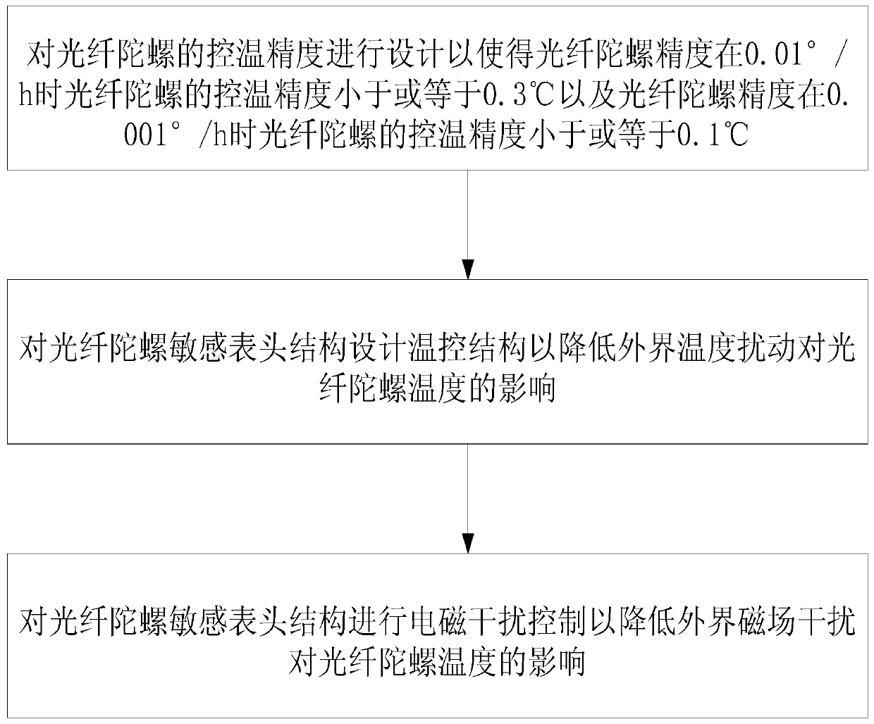
[0003] The present invention provides a fiber optic gyro temperature control structure and a method for using it, which can solve the problem that the temperature compensation method in the prior art is difficult to meet the accuracy of high-precision fiber optic gyro instruments Asked technical questions

Method used


Image

  • Fiber-optic gyroscope temperature control structure and method for using same

Examples


Embodiment Construction

[0017] It should be noted that, in the case of no conflict, the embodiments in the present application and the features in the embodiments can be combined with each other. The following will clearly and completely describe the technical solutions in the embodiments of the present invention with reference to the accompanying drawings in the embodiments of the present invention. Obviously, the described embodiments are only some, not all, embodiments of the present invention. The following description of at least one exemplary embodiment is merely illustrative in nature and in no way taken as limiting the invention, its application or uses. Based on the embodiments of the present invention, all other embodiments obtained by persons of ordinary skill in the art without creative efforts fall within the protection scope of the present invention.

[0018] It should be noted that the terminology used here is only for describing specific implementations, and is not intended to limit t...


PUM


Abstract

The invention provides a fiber-optic gyroscope temperature control structure and a method for using the same. The structure includes: first, second and third thermal insulation layers, first and second temperature control layers, a first heat insulation layer, a first temperature control layer, a second heat insulation layer, a second temperature control layer and a third heat insulation layer, all of which are sequentially arranged. The first heat insulation layer is arranged on the outer side of a fiber-optic gyroscope sensitive gauge outfit structure; the first heat insulation layer is usedfor carrying out heat insulation on the fiber-optic gyroscope sensitive gauge outfit structure; the first temperature control layer is used for maintaining the working temperature of the first temperature control layer within a first set temperature range; the second heat insulation layer is used for conducting heat insulation on the first temperature control layer, the second temperature controllayer is used for maintaining the working temperature of the second temperature control layer within a second set temperature range, and the third heat insulation layer is used for conducting heat insulation on the second temperature control layer to reduce the influence of external temperature disturbance on the temperature of the second temperature control layer. By applying the technical scheme of the invention, the technical problem that the temperature compensation method in the prior art is difficult to meet the precision requirement of the high-precision optical fiber gyroscope meter is solved.

Description

technical field [0001] The invention relates to the technical field of fiber optic gyroscope temperature control, in particular to a fiber optic gyroscope temperature control structure and a method for using the same. Background technique [0002] With the improvement of fiber optic gyro technology, high precision, miniaturization, and low cost have become the development direction of fiber optic gyroscopes. However, due to the fundamental problems of fiber optic gyroscopes, fiber optic gyroscopes have strong temperature sensitivity, which can generally be improved by temperature compensation. The adaptability of the fiber optic gyroscope to the variable temperature environment improves the accuracy of the fiber optic gyroscope, but at the level of inertial fiber optic gyroscope accuracy, only relying on the temperature compensation method can no longer meet the accuracy requirements of the inertial class high-precision fiber optic gyroscope. The temperature of the sensitive...

Claims


Application Information

Patent Timeline
IPC IPC(8): G01C19/64G01C19/72G05D23/20
CPCG01C19/64G01C19/721G05D23/20
Inventor 杨纪刚欧姮姜千红于晓之李宗利徐广海胡斌张红线毕聪志
Owner BEIJING AUTOMATION CONTROL EQUIP INST
Why Eureka
Eureka Blog
Learn More