Method for inhibiting residual rotation light angle of atomic spin gyroscope

A kind of atomic spin and gyroscope technology, which is applied to steering induction equipment and other directions, can solve the problem of not giving a theoretical unified adjustment standard, and cannot completely eliminate the residual optical rotation angle of the detection optical path.

Pending Publication Date: 2022-01-21
BEIHANG UNIV
View PDF0 Cites 1 Cited by
  • Summary
  • Abstract
  • Description
  • Claims
  • Application Information

AI Technical Summary

Problems solved by technology

This type of method has the disadvantage that the signal offset can only be adjusted at a fixed wavelength of the detection laser, and the offset adjustment at this time cannot completely elimin

Method used


Image

  • Method for inhibiting residual rotation light angle of atomic spin gyroscope
  • Method for inhibiting residual rotation light angle of atomic spin gyroscope

Examples


Example Embodiment

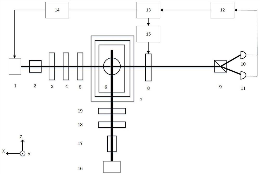
[0029] Below with the accompanying drawings ( figure 1 The present invention will be described.

[0030] figure 1 It is a schematic diagram of the structural principle of an atomic spin gyroscope system for suppressing the residual rotary optical angle of atomic spin gyro. refer to figure 1 As shown, a method of suppressing the residual rotational angle of the atomic spin gyroscope, wherein the liquid crystal phase retarder 8 is provided on the detection optical path between the alkali metal gas chamber 6 and the Wolacton prism 9, the The liquid crystal phase retarder 8 adjusts the detection light phase to suppress the residual direction of rotation based on the feedback control signal formed by the gyroscope output signal. The detection light passes through the alkali metal chamber 6 is a linear polarized light, and the linearly polarized light carrys a rotational angular information due to the presence of angular rate input, and the residual rotation angle is caused by optical ...


PUM


Abstract

The invention relates to a method for inhibiting a residual rotation optical angle of an atomic spin gyroscope, which comprises the following steps of: emitting detection laser from a detection laser, sequentially passing through an optical isolator ISO, a polarizer, a 1/2 wave plate and a polarization analyzer to become linearly polarized light, entering an alkali metal gas chamber, and emitting the linearly polarized light carrying angular rate information out of the gas chamber through a small hole in a magnetic shielding layer, dividing emergent detection light into two independent beams of detection light through a liquid crystal phase delayer and a Wollaston prism, receiving the two independent beams of detection light by two photoelectric detectors, transmitting thetwo independent beams of detection light to a data processing unit through a lock-in amplifier, and enabling the data processing unit to control a detection laser through a laser tube temperature controller; using the liquid crystal controller to controll the liquid crystal phase delayer to suppress the residual rotation angle, so that the signal bias of the gyroscope is reduced, the zero-bias stability of the gyroscope is improved, and the comprehensive performance of the gyroscope is improved.

Description

technical field [0001] The invention relates to an atomic spin gyroscope output signal error compensation technology, in particular to a method for suppressing the residual rotational light angle of an atomic spin gyroscope. Background technique [0002] Compared with the traditional inertial measurement instrument, the atomic spin inertial measurement instrument based on spin-exchange relaxation-free (Spin-Exchange Relaxation-Free, SERF) has the potential to achieve higher accuracy or smaller volume under the same volume. , which has aroused extensive research interest. Bias stability is an important index to evaluate the performance of gyroscopes, and the scale factor error is one of the important error items that limit the bias stability of SERF gyroscopes. [0003] In the SERF atomic spin gyroscope, reducing the bias of the atomic spin precession signal is one of the methods to improve the gyroscope scale factor error, because when the output bias of the gyroscope is no...

Claims


Application Information

Patent Timeline
IPC IPC(8): G01C19/58
CPCG01C19/58
Inventor 王卓秦博东王瑞钢魏瑶刘祀浔袁琪
Owner BEIHANG UNIV
Why Eureka
Try Eureka