MEMS gyroscope

A technology of gyroscopes and ring structures, applied in the field of gyroscopes, can solve the problems of low bias stability, affecting detection performance, and low sensitivity

Pending Publication Date: 2021-04-20
AAC TECH NANJING
View PDF6 Cites 2 Cited by
  • Summary
  • Abstract
  • Description
  • Claims
  • Application Information

AI Technical Summary

Problems solved by technology

However, the disc-shaped gyroscope is limited in structure and space layout, such as the patent of the traditional Disc gyroscope with the patent number US7581443B2, and referring to the attached Figure 4 In the normalized displacement map of the traditional Dsic gyro, some areas are not or less involved in vibration and sensitivity, and the chip area utilization rate is low, resulting in low sensitivity and low bias stability, which affects its detection performance

Method used


Image

  • MEMS gyroscope
  • MEMS gyroscope
  • MEMS gyroscope

Examples


Embodiment 1

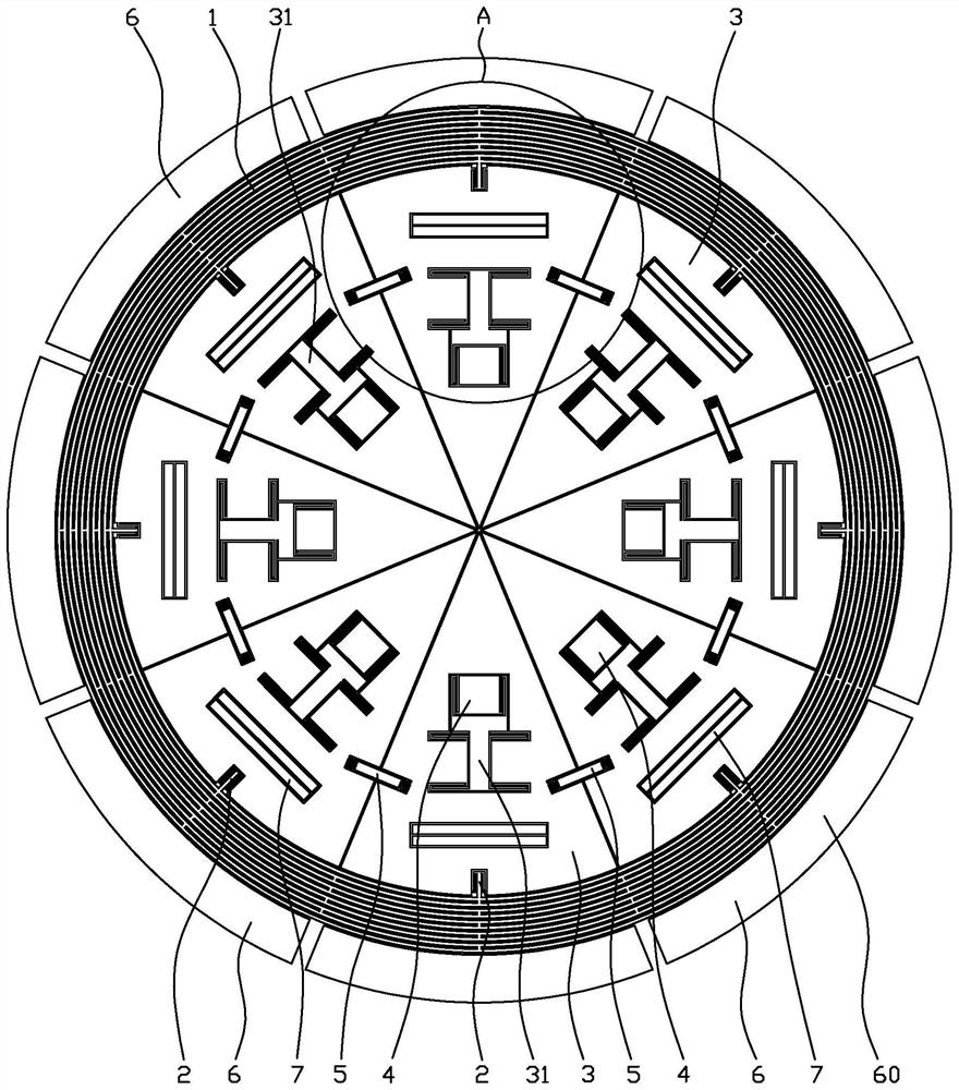
[0035] Such as figure 1 As shown, the MEMS gyroscope includes a ring structure 1, a first coupling structure 2 connected to the ring structure 1, a mass block 3 connected to the end of the first coupling structure 2 away from the ring structure 1, and an anchor point 4 connected to the mass block 3 , the second coupling structure 5 connected between adjacent mass blocks 3 and the transducer assembly 60 connected to the ring structure 1 and the mass block 3, the MEMS gyroscope includes 4N equiangular arrangements around the center of the ring structure 1 and The mass block 3 with the same size, N is an integer greater than or equal to 2, the mass block 3 includes a main body 30 connected to the first coupling structure 2 and having a receiving groove 33 inside, and an elastic structure connected to the main body 30 and located in the receiving groove 33 31 , the anchor point 4 is disposed in the receiving groove 33 and connected with the elastic structure 31 .

[0036] The ma...

Embodiment 2

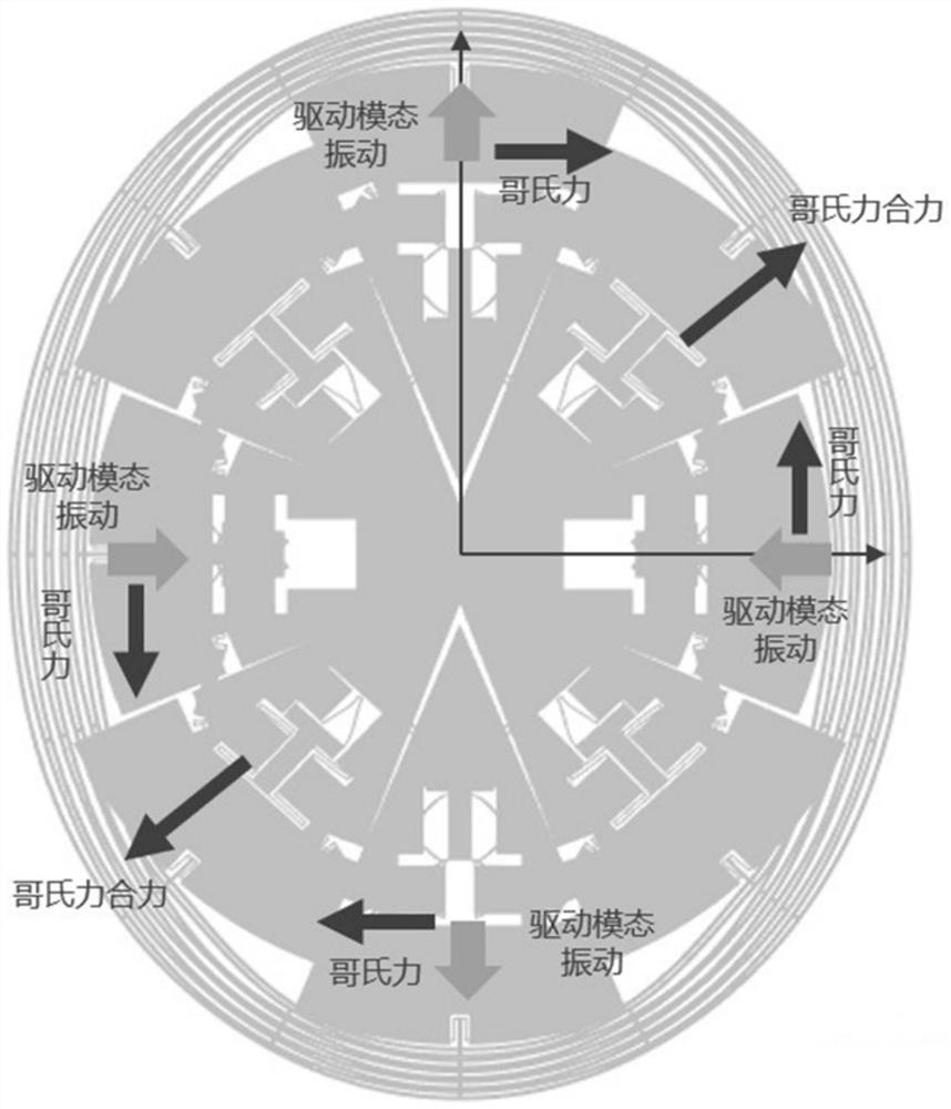
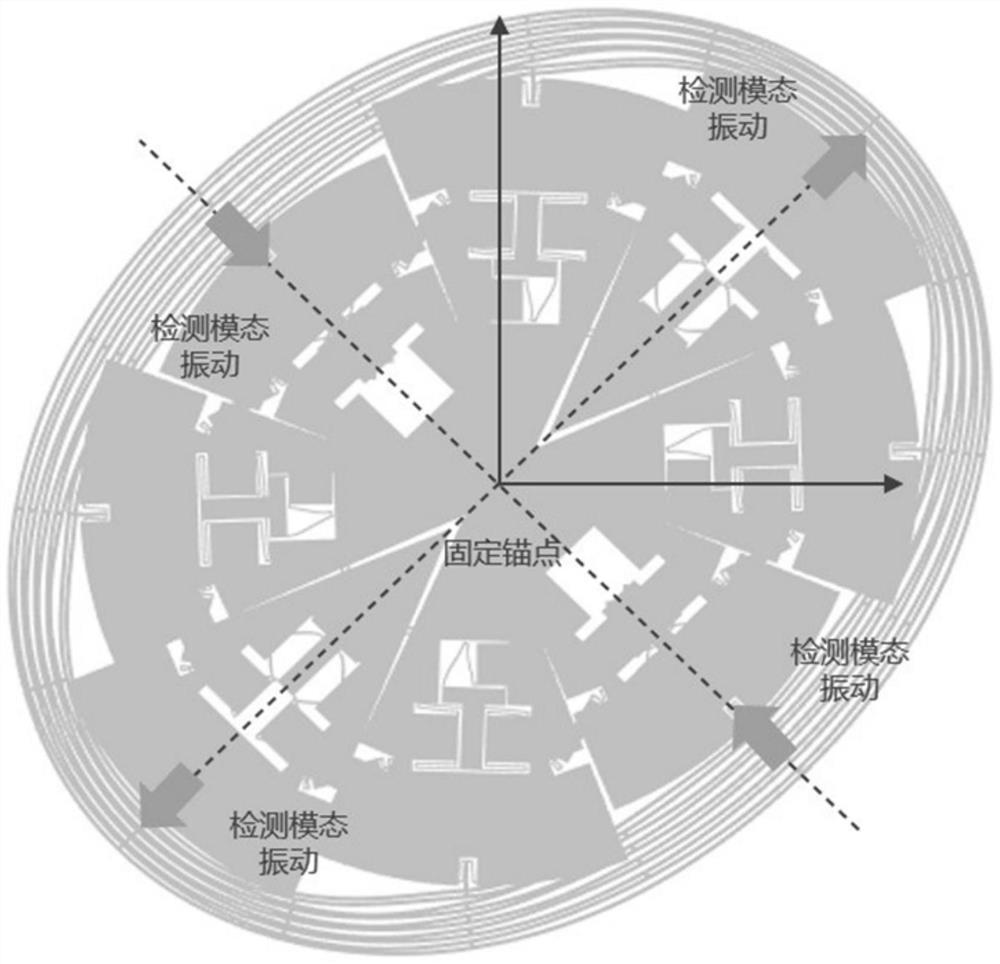
[0044] Such as Figure 7 As shown, the difference with Embodiment 1 is that in this embodiment, N is 3, that is, the mass block 3 has 12 pieces, and now the vibration mode of the MEMS gyroscope is Figure 8 As shown, the detection modality is as Figure 9 shown. In some embodiments, N can be 4, 5, 6, etc., so that the number of masses reaches 16, 20, 24, etc.


PUM


Abstract

The invention provides an MEMS gyroscope which comprises an annular structure, a first coupling structure connected to the annular structure, mass blocks connected to the first coupling structure, anchor points connected with the mass blocks, second coupling structures connected between the adjacent mass blocks and transduction assemblies connected to the annular structure and the mass blocks. The MEMS gyroscope comprises 4N mass blocks arranged around the center of the annular structure at equal angles, N is an integer larger than or equal to 2, each mass block comprises a main body connected with the first coupling structure and provided with a containing groove and an elastic structure connected to the main body and located in the containing groove, and the anchor points are arranged in the containing grooves and connected with the elastic structures. According to the scheme, the area utilization rate of the chip region can be improved, the sensitivity is increased, the bias stability is improved, the detection performance is improved, and the mechanical noise is reduced.

Description

【Technical field】 [0001] The invention belongs to the technical field of gyroscopes, in particular to MEMS gyroscopes. 【Background technique】 [0002] Micro-mechanical gyroscopes, namely MEMS (Micro Electro Mechanical systems) gyroscopes, are a typical angular velocity microsensor. Due to their small size, low power consumption and convenient processing, they are widely used in the consumer electronics market. In recent years, with the gradual improvement of the performance of MEMS gyroscopes, they are widely used in automotive, industrial, virtual reality and other fields. [0003] MEMS gyroscopes can be divided into two types: linear vibration tuning fork gyroscopes and disk-shaped gyroscopes. Among them, the driving mode shape and detection mode shape of the disk-shaped gyroscope are degenerate, with high sensitivity and simple structure. Gradually become a more practical high-performance gyroscope. However, the disc-shaped gyroscope is limited in structure and space la...

Claims


Application Information

Patent Timeline
IPC IPC(8): G01C19/5621
CPCG01C19/5621
Inventor 占瞻马昭阚枭杨珊李杨谭秋喻洪燕黎家健
Owner AAC TECH NANJING
Why Eureka
Try Eureka