Piezoelectric resonator element, piezoelectric, resonator, and piezoelectric oscillator

a technology of piezoelectric resonator and resonator, which is applied in the direction of piezoelectric/electrostrictive device details, device details, device material selection, etc., to achieve the effect of increasing the effect of forming the groov

Inactive Publication Date: 2008-05-06
SEIKO EPSON CORP
View PDF13 Cites 44 Cited by
  • Summary
  • Abstract
  • Description
  • Claims
  • Application Information

AI Technical Summary

Benefits of technology

[0037]Further, in order to increase the effect of forming the groove, the piezoelectric resonator element in exemplary embodiments of the present invention has main surfaces; and a groove formed on at least one of the main surfaces; the piezoelectric resonator element capable of forming a thickness shear vibration as a main vibration; the groove may be formed in a way that, on the main surfaces, one part of the groove faces another part of the groove, the groove sandwiching a center part, or the groove surr...

Problems solved by technology

H9-93076 and Japanese Unexamined Patent Publication No. 2001-257558 there is a problem because bot...

Method used


Image

  • Piezoelectric resonator element, piezoelectric, resonator, and piezoelectric oscillator
  • Piezoelectric resonator element, piezoelectric, resonator, and piezoelectric oscillator
  • Piezoelectric resonator element, piezoelectric, resonator, and piezoelectric oscillator

Examples


first exemplary embodiment

The First Exemplary Embodiment

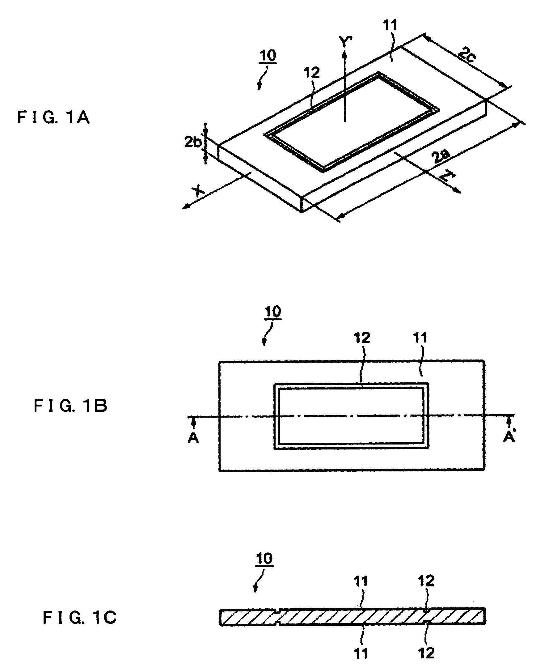
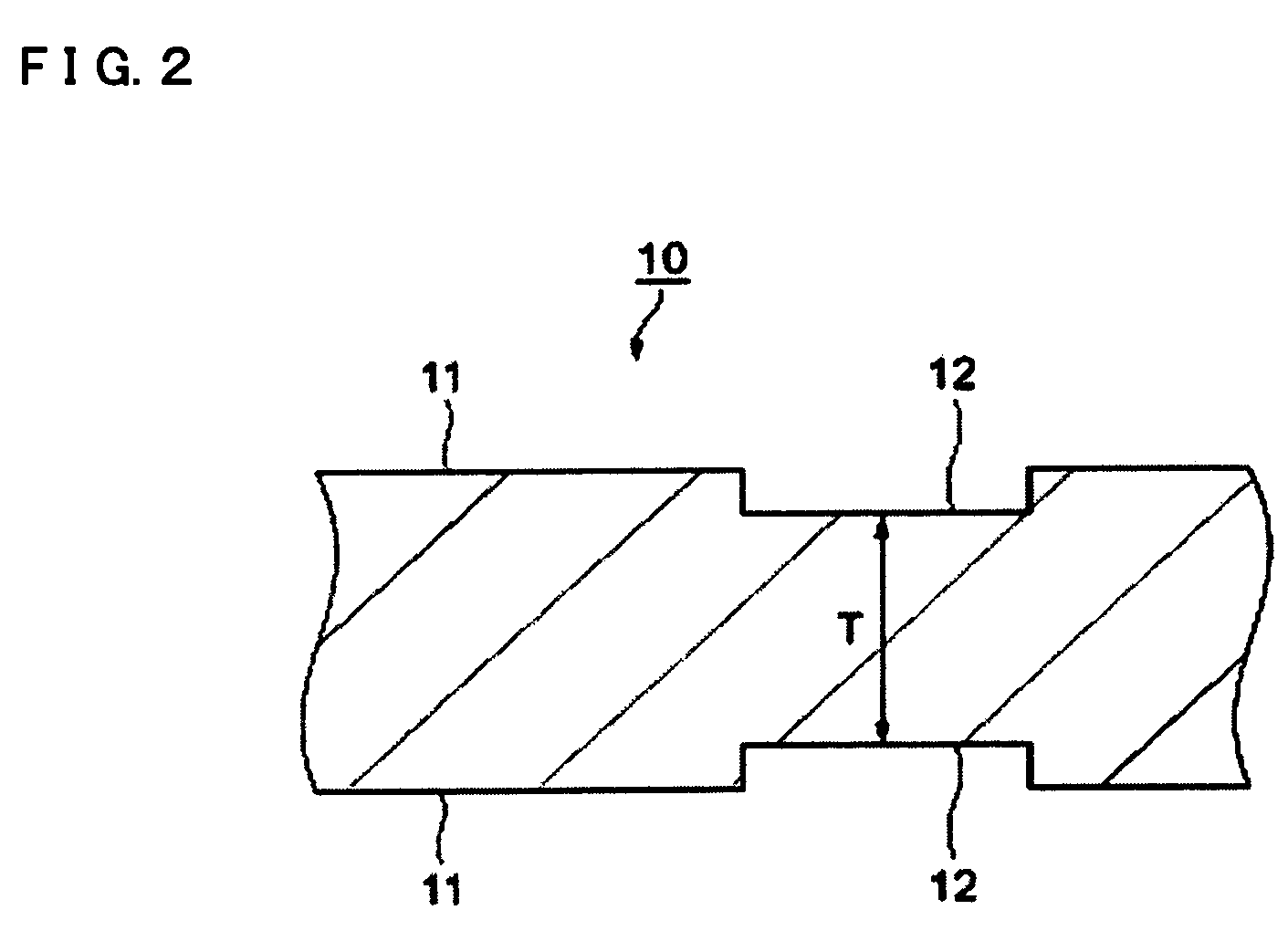
[0078]FIGS. 1A-1C and FIG. 2 are schematic drawings of the resonator element describing the first exemplary embodiment. FIG. 1A is a perspective view of the resonator element, FIG. 1B is a top view of the resonator element, FIG. 1C is a sectional drawing of section A-A in FIG. 1B and FIG. 2 is an enlarged drawing of the groove in FIG. 1C.

[0079]A resonator element 10, which serves as a piezoelectric resonator element, is designed to have, for example, 27 MHz of resonance frequency, a side X ratio 33 (the ratio of the size in the direction of the X axis of the resonator element against its thickness), and a side Z ratio 21 (the ratio of the size in the direction of the Z′ axis of the resonator element against its thickness). Here, the thickness of the center part of the resonator element 10 is about 62 μm.

[0080]The Y′ and Z′ axes of the resonator element 10 are the new axes made by rotating around the X axis toward the positive direction of X, clockwise, ...

second exemplary embodiment

The Second Exemplary Embodiment

[0106]Hereafter, the second exemplary embodiment, where two grooves are provided in a resonator element, is described.

[0107]FIGS. 10A-10C and FIG. 11 are schematics of the resonator element describing the second exemplary embodiment. FIG. 10A is a perspective view of the resonator element, FIG. 10B is a top view of the resonator element, FIG. 10C is a sectional drawing of the section A-A in FIG. 10B, and FIG. 11 is an enlarged drawing of the groove part in FIG. 10C.

[0108]In FIGS. 10A-10C and FIG. 11, the same drawing elements are used for the same structure as those in the first exemplary embodiment.

[0109]In the main surface 11 of the resonator element 10, circumference grooves, which are the first groove 12 as well as the second groove 13, are formed so as to surround the center part of the main surface 11 with a quadrangle. The first grooves 12 as well as the second grooves 13 are formed on the front and back of the main surfaces of the resonator ele...

third exemplary embodiment

The Third Exemplary Embodiment

[0119]Hereafter, the third exemplary embodiment, where three grooves are provided in a resonator element, is described.

[0120]FIGS. 14A-14C and FIG. 15 are schematic drawings of the resonator element describing the third exemplary embodiment. FIG. 14A is a perspective view of the resonator element, FIG. 14B is a top view of the resonator element, FIG. 14C is a sectional drawing of the section A-A in FIG. 14B, and FIG. 15 is an enlarged drawing of the groove part in FIG. 14C.

[0121]In FIGS. 14A-14C and FIG. 15, the same drawing elements are used for the same structure as those of the first exemplary embodiment and the second exemplary embodiment.

[0122]As shown in FIG. 14A, as well as in FIG. 14B, in the main surface 11 of the resonator element 10, circumference grooves, which are the first groove 12, the second groove 13, and the third groove 14, are formed so as to surround the center part of the main surface 11 with a quadrangle. The first grooves 12, th...


PUM


Abstract

Exemplary embodiments provide a piezoelectric resonator element, to reduce the reaching of an attenuating vibration of a main vibration to a marginal edge of the piezoelectric resonator element, as well as to stabilize an oscillating-frequency without worsening the CI value, nor inducing another vibration mode. The piezoelectric resonator element having a thickness shear vibration as a main vibration, a first groove and a second groove formed so as to surround the center part of a main surface, and the thickness at the first groove and the second groove structured to be between 70% to 96%, inclusive, of the thickness of the center part of the resonator element.

Description

BACKGROUND[0001]Exemplary embodiments relate to a piezoelectric resonator element, a piezoelectric resonator, and a piezoelectric oscillator; where the piezoelectric resonator element is capable of forming a thickness shear vibration as a main vibration, declining the reaching of an attenuating vibration of the main vibration to a marginal edge of the piezoelectric resonator element, and reducing the vibration displacement in the attenuating vibration of the piezoelectric resonator element.[0002]Related art piezoelectric resonators are widely used as a base-frequency-signal source in various electronic devices or communication devices. Among piezoelectric resonators, AT cut quartz crystal resonators can outstandingly maintain frequency stability in wide range of temperatures, and are outstandingly tolerant against time duration, and hence are widely used for various devices, such as electronic devices and mobile communication devices, etc.[0003]AT cut quartz crystal resonator is com...

Claims


Application Information

Patent Timeline
IPC IPC(8): H01L41/04H01L41/08H01L41/18H03B5/32H03H3/02H03H9/02H03H9/15H03H9/19
CPCH03H9/02086H03H9/0519H03H9/0547H03H9/17
Inventor TANAKA, MASAKO
Owner SEIKO EPSON CORP
Why Eureka
Try Eureka