

Apparatus and method for preparing platelet rich plasma and concentrates thereof
a technology of platelet and concentrate, which is applied in the direction of centrifuges, membranes, separation processes, etc., can solve the problems of unconcentrated plasma fraction, unfavorable ineffective plasma fraction as hemostat or tissue adhesive, etc., and achieve the effect of improving the amount of platelets
- Summary
- Abstract
- Description
- Claims
- Application Information
AI Technical Summary
Benefits of technology
Problems solved by technology
Method used
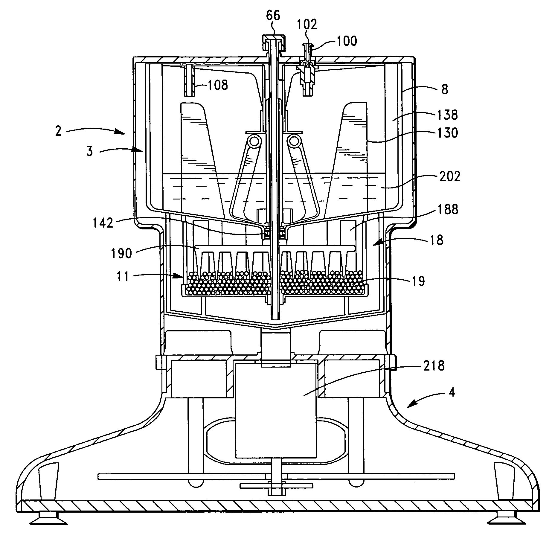
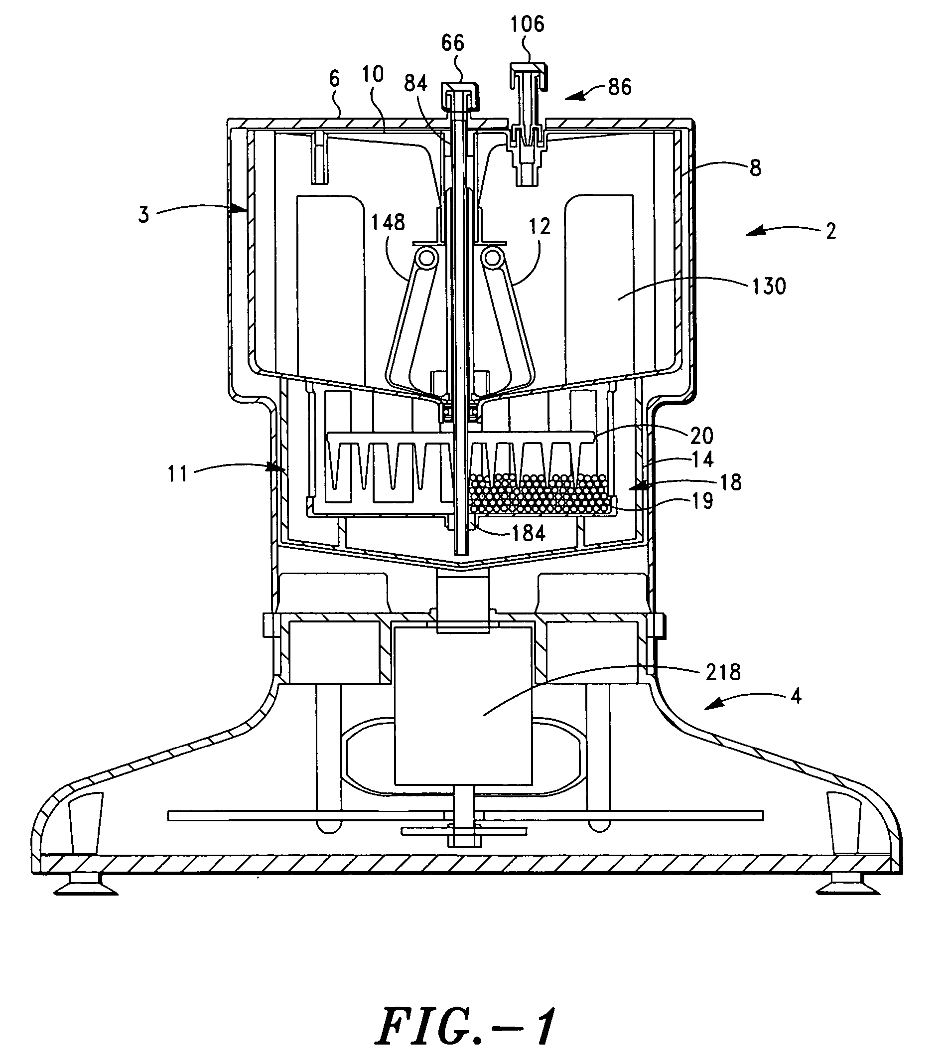
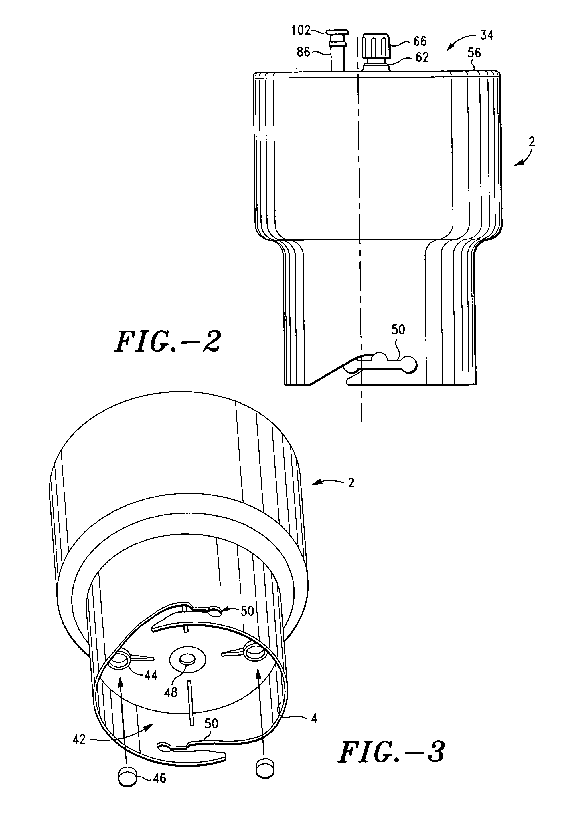
Image

Examples
example
Standard System Operation
[0118]Blood was processed with a device as shown and described in this application.[0119]1) The initial spin was continued for 10 seconds at 250 rpm. This spin allows beads to be flung out into the cage under sufficiently low rpm that the initial imbalance does not generate excessive vibration. The outer ends of the rakes (the outermost tines) level the beads around the perimeter of the basket to balance the beads.[0120]2) The erythrocytes were separated with the an erythrocyte separation spin of 3200 rpm for 90 seconds, packing the erythrocytes into the depth filter.[0121]3) The PRP was concentrated by slowing the spin to 50 rpm for 45 seconds, draining PRP into the concentrator chamber and mixing the PRP with the beads.[0122]4) The PRP concentrate was then removed from the beads by a final high-speed spin at 3200 rpm for 45 seconds.
The rates of acceleration and deceleration between stages were moderated to reduce vibration.
[0123]The process parameters were...
PUM
| Property | Measurement | Unit |
|---|---|---|
| centrifugal speeds | aaaaa | aaaaa |
| rotational speed | aaaaa | aaaaa |
| rotation speed | aaaaa | aaaaa |
Abstract
Description
Claims
Application Information