

Dilution air hole in a gas turbine combustion chamber with combustion chamber tiles
a gas turbine and combustion chamber technology, applied in the combustion process, hot gas positive displacement engine plants, lighting and heating apparatus, etc., can solve the problems of insufficient cooling air for fuel preparation, and a large amount of cooling air will leak through the gap, so as to achieve the effect of safety of operation
- Summary
- Abstract
- Description
- Claims
- Application Information
AI Technical Summary
Benefits of technology
Problems solved by technology
Method used
Image

Examples
Embodiment Construction
[0025]This detailed description should be read in conjunction with the summary above, which is incorporated by reference in this section.
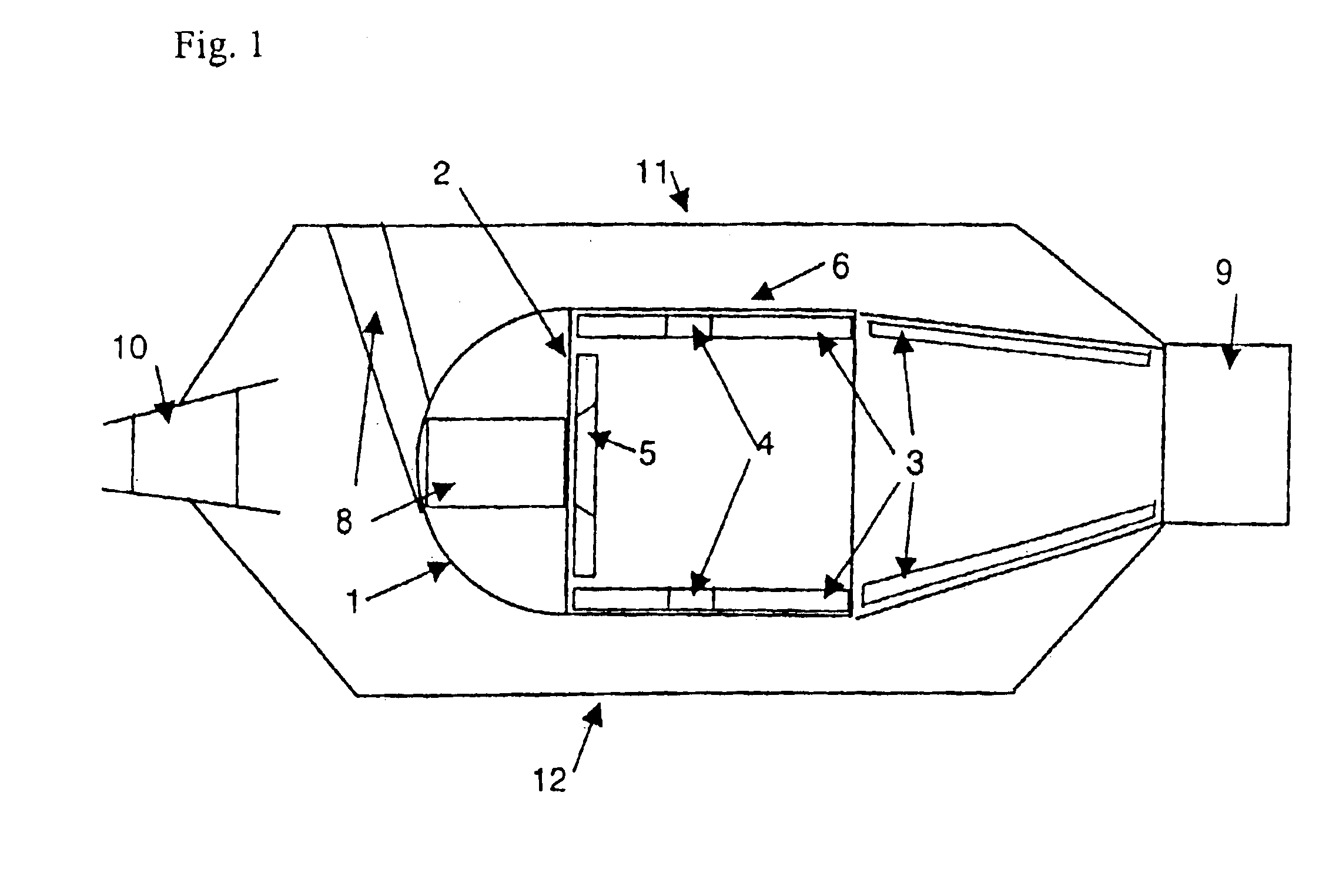
[0026]FIG. 1 shows a schematic sectional side view of a gas turbine combustion chamber according to the state of the art. Here, a hood 1 of a combustion chamber head is shown. Reference numeral 2 indicates a base plate, while reference numeral 3 designates combustion chamber tiles. The combustion chamber tiles 3 include dilution air holes 4 and are attached to a supporting structure 6. Reference numeral 5 indicates a heat shield with an opening for a burner 8. At the exit of the combustion chamber, a turbine nozzle guide vane 9 is shown in schematic representation. Reference numeral 10 indicates a guide vane at the compressor exit. A combustion chamber outer casing 11 and a combustion chamber inner casing 12 enclose the combustion chamber.
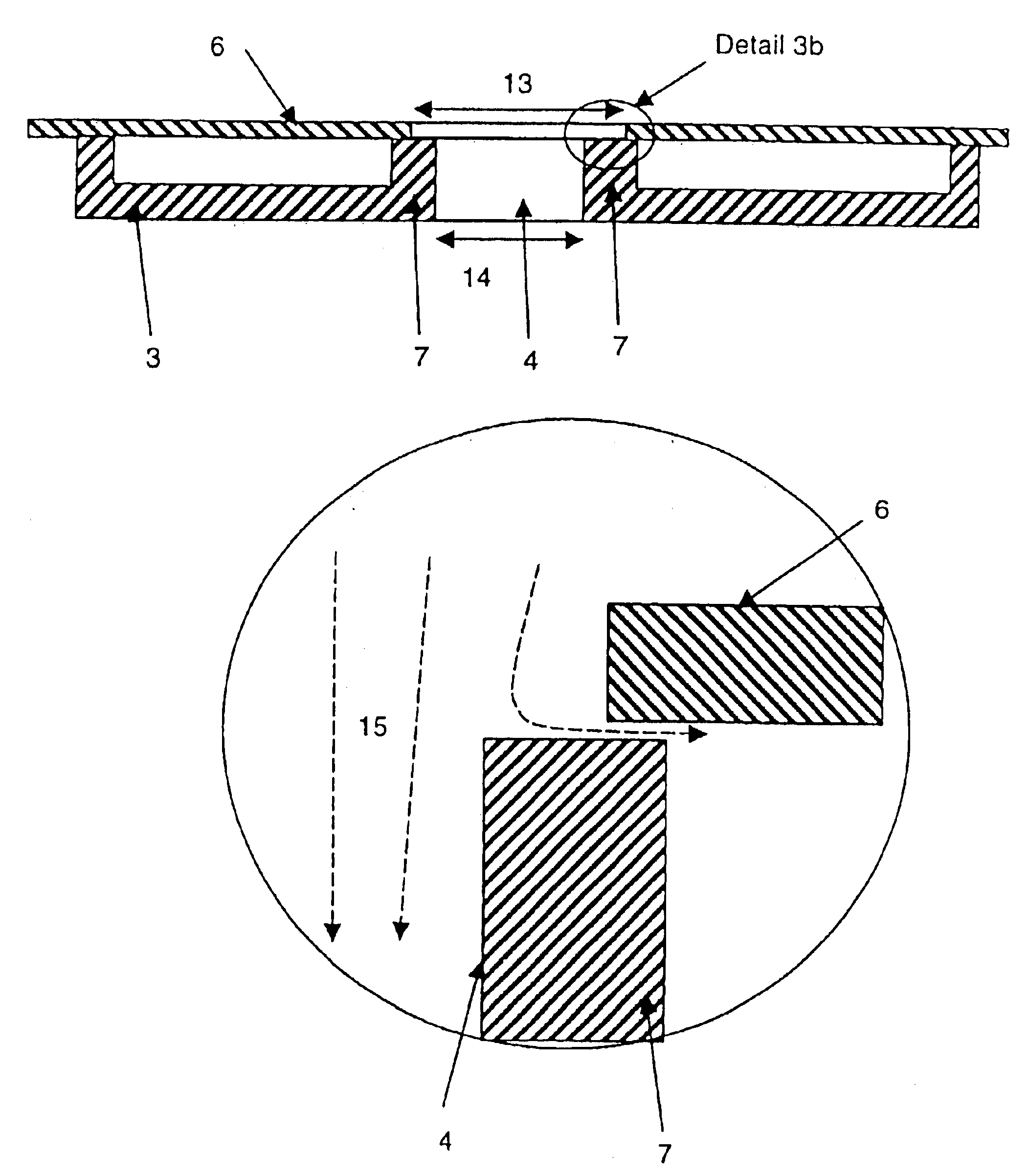
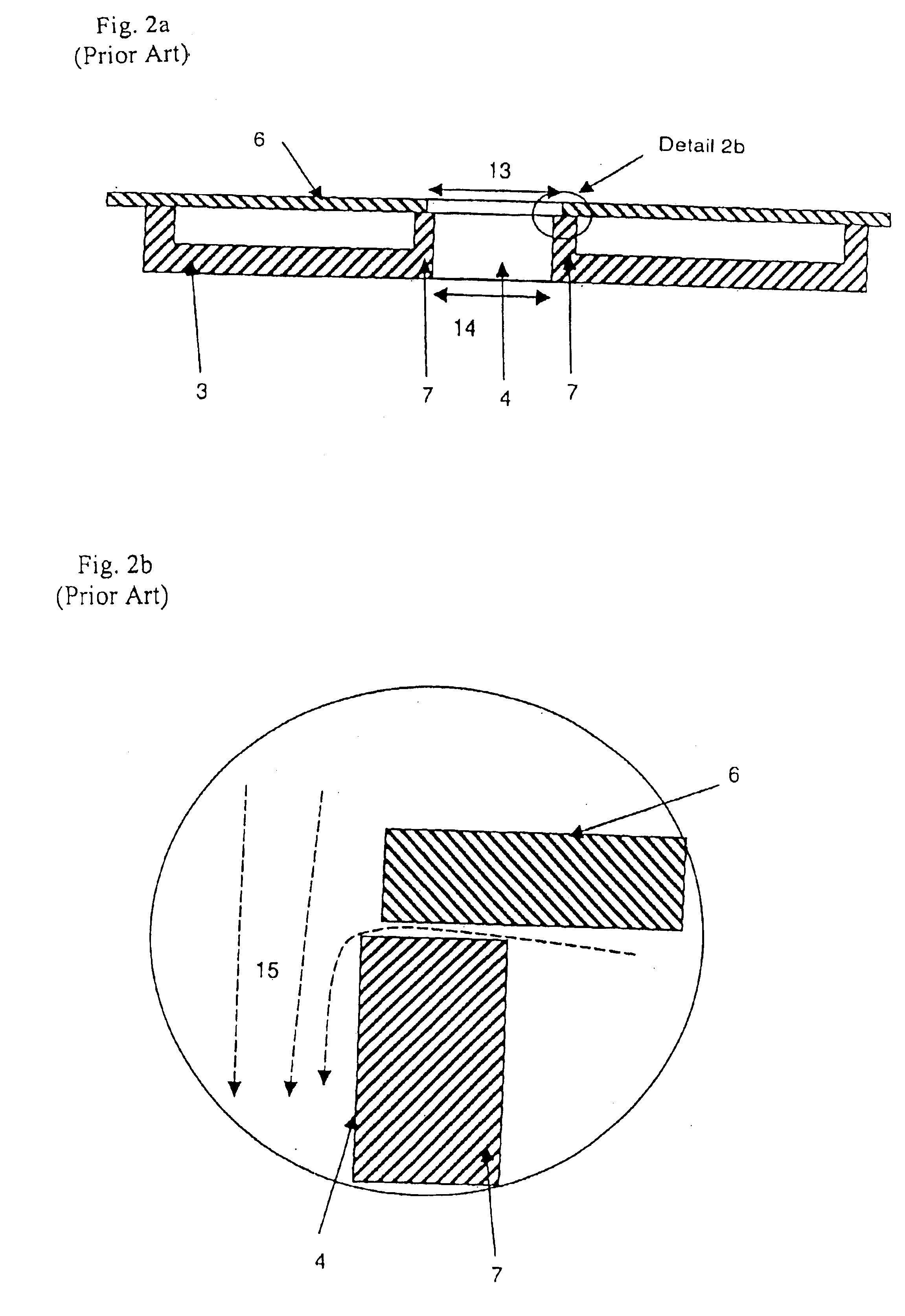
[0027]FIGS. 2a and 2b show the form of a dilution air hole 4 of the combustion chamber tile 3 and of a correspo...
PUM
 Abstract
Description
Claims
Application Information