Filter cartridge mounting assembly for robotic pool and tank cleaner

a technology for cleaning tanks and filter cartridges, which is applied in the direction of hollow article cleaning, filtration separation, and separation processes, etc., can solve the problems of frequent cleaning and maintenance of filters, inability to clean and maintain filters, and inability to quickly fill the interior of filters and filters with debris,

Inactive Publication Date: 2013-06-20
AQUA PRODS
View PDF0 Cites 35 Cited by
  • Summary
  • Abstract
  • Description
  • Claims
  • Application Information

AI Technical Summary

Benefits of technology

[0019]As will be understood by those of ordinary skill in the art, the open ends of the cartridge filter body can be fitted with annular seals of resilient material that are provided with a groove that snugly receives the pleated filter and prevents water from by-passing the filter medium.

Problems solved by technology

Although the hinged filter lid enables easy access to the filter to enable cleaning or replacement, cleaning and maintenance of the filter can be frequently required, which is undesirable.
Specifically, since the contaminated water flows directly into the interior of the filter from the water inlet, the interior of the filter and can quickly fill with debris which clogs the mesh or screen material which forms the filter body.
Disadvantageously, the user must blindly attempt to achieve this alignment without dislodging the bottom end of the filter from its desired position against the interior surface of the base plate.
Because the pump motor is attached to the housing cover, a user must attempt to complete this reassembly, but the user is blind to the positioning.
As a consequence, such blind assembly makes reassembly a very difficult task since misalignment and improper seating of the filter can result in a crimped or damaged the filter.
The misaligned or damaged filter could allow debris to enter directly into the interior of the filter that normally contains only filtered water, and such debris could damage the pump propeller.
Another disadvantage of the cleaner of the '927 patent is that the housing is fabricated from a plastic material which can flex upwards and downwards, respectively, when the pump starts and stops.
This vertical movement can dislocate or displace the contact seals between the underside of the housing cover and the interior surface of the base plate, and thereby allow debris to undesirably enter the interior portion of the filter and damage the pump propeller.

Method used


Image

  • Filter cartridge mounting assembly for robotic pool and tank cleaner
  • Filter cartridge mounting assembly for robotic pool and tank cleaner
  • Filter cartridge mounting assembly for robotic pool and tank cleaner

Examples


Embodiment Construction

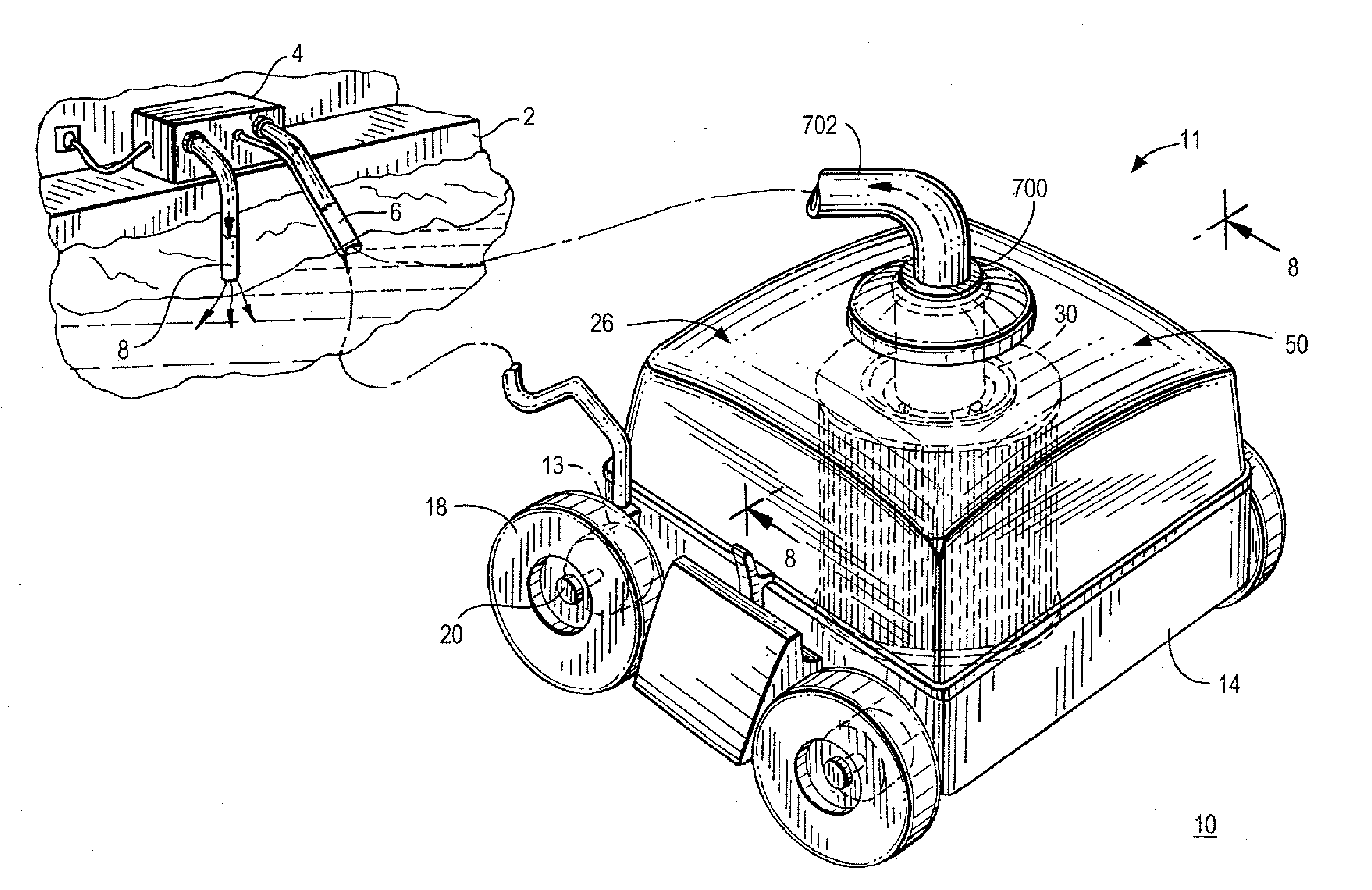
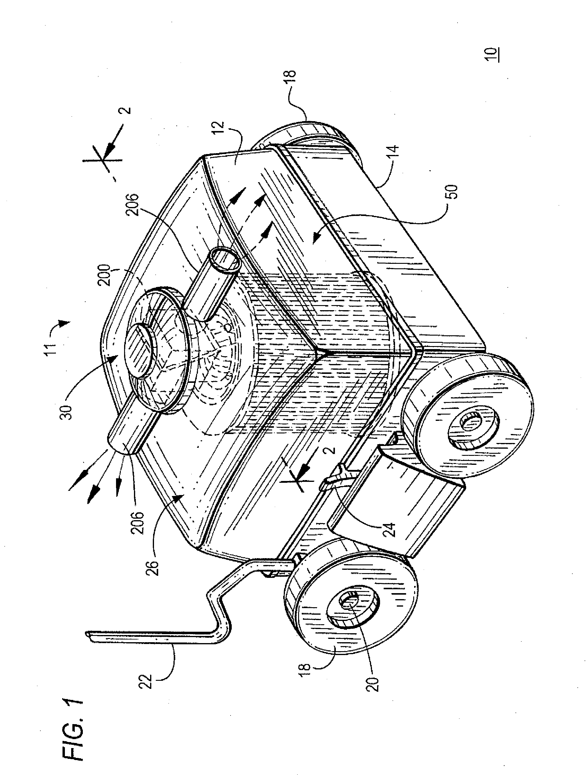
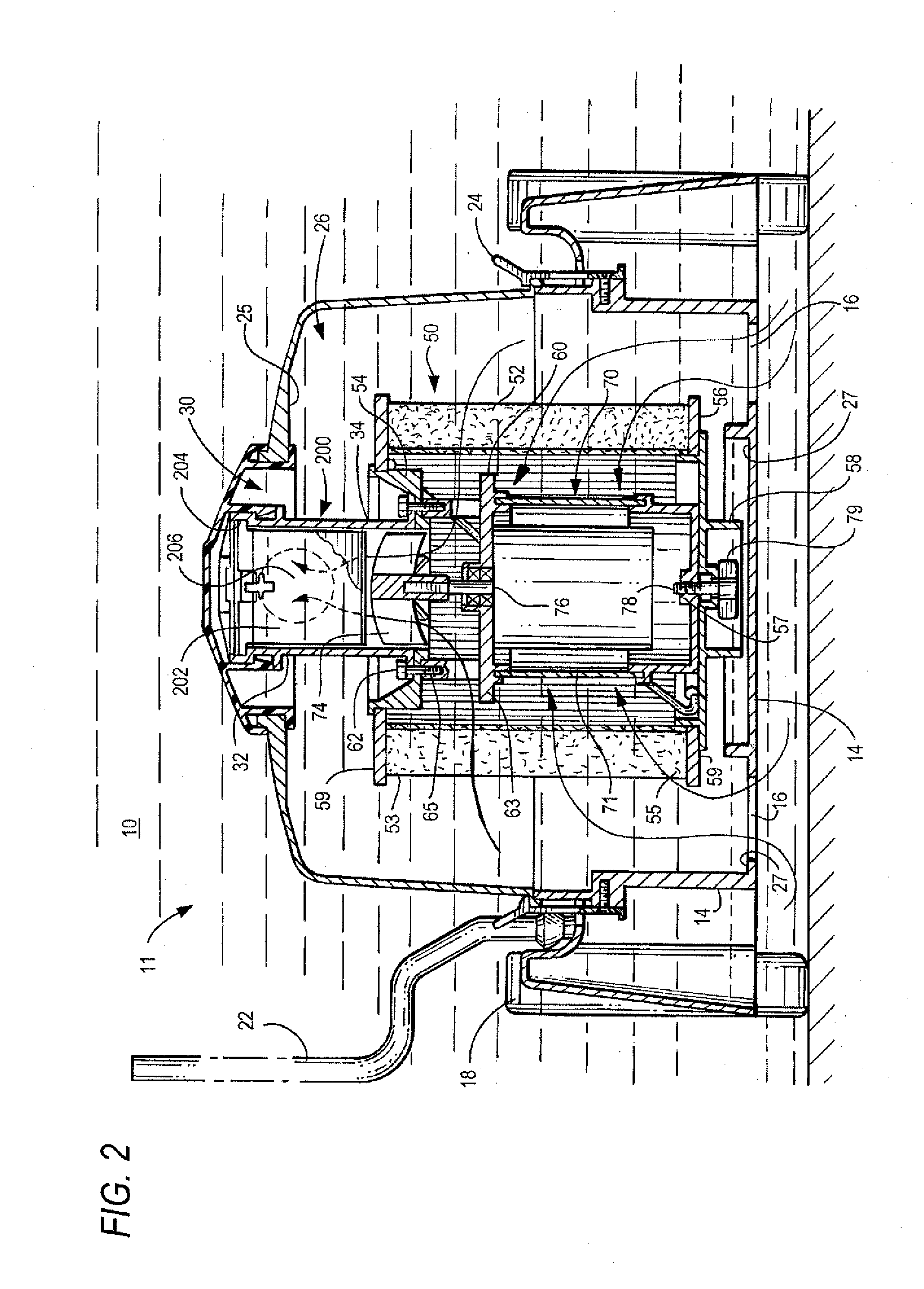
[0036]For purposes of providing a better understanding the invention, terms connoting direction and positioning of components are defined as follows:[0037]longitudinal axis of the cleaner is defined as extending centrally through the cleaner in the direction of movement;

[0038]movement of the cleaner in a forward direction is the direction that the cleaner is presently being propelled or driven along its cleaning path;

[0039]movement of the cleaner in a reverse direction is a direction that is opposite to the forward direction along the cleaning path;

[0040]the front of the cleaner is defined as the portion of the cleaner extending perpendicular along the longitudinal axis in the forward direction of movement as the cleaner travels along its cleaning path;

[0041]“top”, “bottom”, “upper” and “lower” are adjectives that denote different cleaner components, as well as define the relative positioning of such components with respect to a central vertical axis extending centrally through the ...


PUM

PropertyMeasurementUnit
pressureaaaaaaaaaa
resilientaaaaaaaaaa
rotationaaaaaaaaaa

Abstract

A self-propelled cleaning apparatus for cleaning a pool includes a housing cover removably fastened to a base to define an interior chamber and rotational supports coupled to the apparatus for moving it over submerged pool surfaces. A water discharge assembly with a water outlet for recirculating filtered water into the pool is coupled to the interior surface of the housing cover. A filter assembly for filtering water and debris flowing from the pool through a water inlet in the base is supported within the interior chamber above the base. A mounting bracket coupled to the water discharge assembly is configured to fixedly position and independently suspend the filter assembly within the interior chamber below the interior surface of the housing cover and above the interior surface of the base.

Description

CROSS-REFERENCE TO RELATED APPLICATION[0001]This patent application claims the benefit of U.S. Provisional Application No. 61 / 576,612, filed Dec. 11, 2011, the content of which is incorporated by reference herein in its entirety.FIELD OF THE INVENTION[0002]The present invention relates to a submersible robotic pool and tank cleaning apparatus, and more specifically to the installation, operation and maintenance of an internal filtering device within the cleaning apparatus for separating and isolating undesirable contaminants and debris from the pool or tank environment.BACKGROUND OF THE INVENTION[0003]Robotic pool cleaning devices are mounted on rotatable supports, such as wheels, brushes and / or tracks, and are propelled or otherwise travel along submerged surfaces of a pool, tank or the like and, through the use of suction, thereby “vacuum” the pool surfaces over which they pass. The pool cleaning devices can be propelled over the surfaces of the pool by a directional or random wat...

Claims


Application Information

Patent Timeline
Patent Type & Authority Applications(United States)
IPC IPC(8): B08B9/08
CPCB08B9/08B01D29/111E04H4/1654B01D2201/291B01D29/21B01D29/114B01D29/15
Inventor ERLICH, GIORACHILTON, SETH
Owner AQUA PRODS
Why Eureka
Try Eureka