Broadband slot antenna

A slot antenna and broadband technology, which is applied in the field of transmitting antennas of radio and television communication systems, can solve the problem that the antenna bandwidth is difficult to meet the new system requirements, and achieve the compact design of the overall structure, the realization of impedance broadband requirements, and the realization of pattern indicators. Effect

Active Publication Date: 2017-02-22
深圳市普方众智精工科技有限公司
View PDF4 Cites 8 Cited by
  • Summary
  • Abstract
  • Description
  • Claims
  • Application Information

AI Technical Summary

Problems solved by technology

Because the antenna system is restricted by the transmission return loss index, the actual existing antenna bandwidth is difficult to meet the new system requirements

Method used


Image

  • Broadband slot antenna
  • Broadband slot antenna
  • Broadband slot antenna

Examples


Embodiment 1

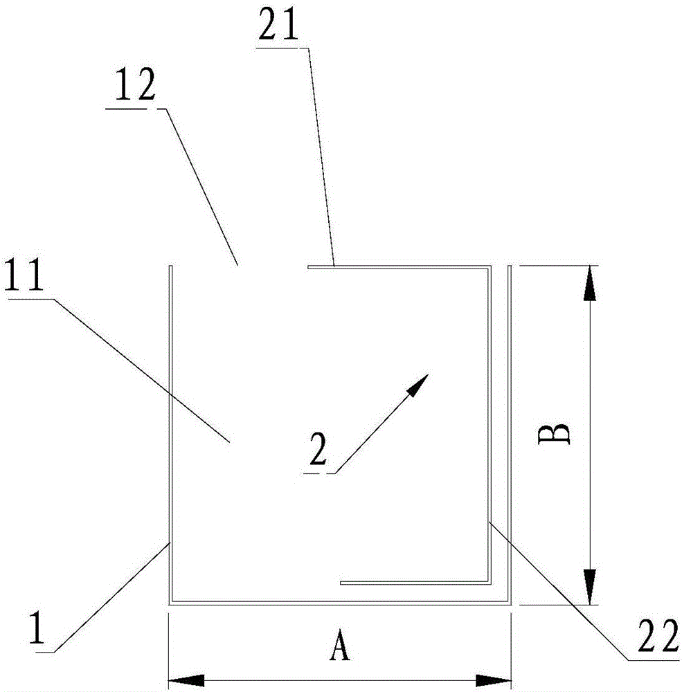
[0042] In the above, the U-shaped waveguide cavity 11 is formed by bending the conductor 1 .

[0043] A common slot antenna is an antenna formed by slits on a conductor surface, also known as a slot antenna. In this structure, by bending the conductor 1 to form a strip-shaped box-shaped antenna body, one side surface is opened to form a gap, and a reflection cavity is formed inside.

Embodiment 2

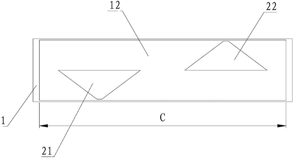
[0045] In the above, the cross-sectional width A of the U-shaped waveguide cavity and the cross-sectional height B of the U-shaped waveguide cavity are both 1 / 4 of the wavelength of the center frequency, and the length C of the slit is equal to the wavelength of the center frequency.

[0046] That is, take the midpoint value of the antenna design frequency to obtain the wavelength λ of the center frequency, then A=1 / 4λ, B=1 / 4λ, and C=1λ. Therefore, it can be designed to meet the frequency resonance impedance matching requirements.

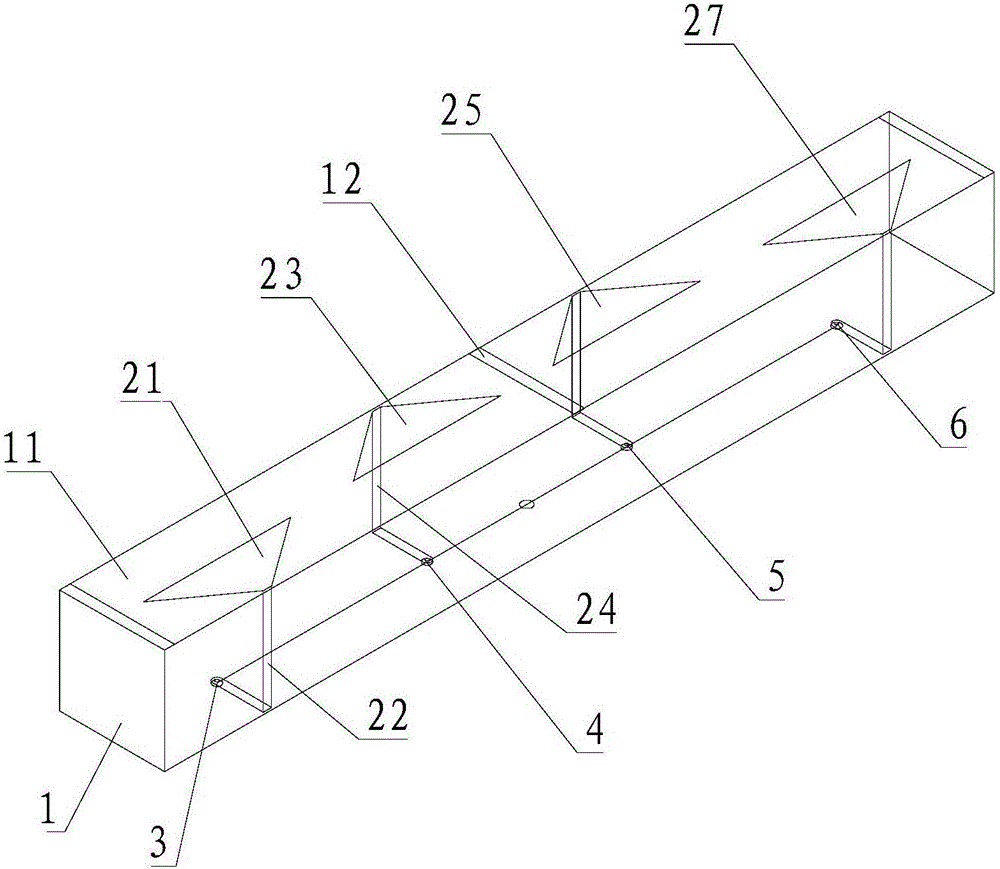
[0047] The size of the reflective cavity is limited by the bandwidth and pattern index of the antenna design. The wider the impedance bandwidth, the larger the corresponding cavity size, but the larger the corresponding reflective surface, the weaker the backward radiation of the antenna, and the more inclined it is to be directional. Therefore, the size of the cavity is limited by the influence of impedance bandwidth and pattern bandwidth. In te...

Embodiment 3

[0050] In the above, the distance between the two feeding points is 1 / 2 of the wavelength of the center frequency.

[0051] In this patented antenna, by adjusting the offset position of the center of the feed point, the resonant frequency changes, the more the offset, the wider the impedance, and the best two feed points are equidistant from the center, and the distance between the two points is 1 / 2λ is preferred.


PUM


Abstract

The invention provides a broadband slot antenna, which comprises a U-shaped waveguide cavity, wherein at least one rectangular slot is formed in one side of an opening of the U-shaped waveguide cavity; two coupling feeds and two feed points are arranged in a way of corresponding to each slot. The broadband slot antenna has the beneficial effects that the antenna uses a U-shaped radiation cavity structure, so that a reflection effect is achieved; meanwhile, a main body part of the antenna is supported; the whole structure design is compact. In addition, the broadband slot antenna is different from a single feed point structure of a conventional slot antenna; the dual-point feed is used; the same-phase feed requirement is met; a directional diagram index is realized; and the impedance broadband requirement can be met. Experiment simulation results show that the two feed points cause two resonant frequencies. In addition, the micro-strip coupling feed is used; the impedance broadband requirement can be met. A coupling feed conduction band is distributed inside the cavity, so that the requirement of a simple structure is met.

Description

technical field [0001] The invention relates to a radio and television communication system transmitting antenna, in particular to a broadband slot antenna. Background technique [0002] In the past ten years, due to the development and maturity of communication technology, the cable TV system has been endowed with more new connotation requirements. The adoption of optical fiber transmission technology, digital technology, two-way transmission technology, Internet interconnection technology, etc., makes the TV program that the cable TV network can transmit farther and faster, the number of transmitted program channels is more, and the transmitted program quality is better. More meaningfully, it realizes two-way interactive transmission of TV programs and data information, and establishes a large-capacity comprehensive information transmission network. The cable TV network will connect thousands of households, and integrate communication, computer, radio and TV program trans...

Claims


Application Information

Patent Timeline
Patent Type & Authority Applications(China)
IPC IPC(8): H01Q13/10H01Q1/50H01Q13/08H01Q1/36
CPCH01Q1/36H01Q1/50H01Q13/08H01Q13/10H01Q13/106
Inventor 刘红波
Owner 深圳市普方众智精工科技有限公司
Why Eureka
Try Eureka