Devices, transmissions and universal mechanical couplings for forces of different magnitudes and directions

A transmission and coupling technology, applied in the direction of transmission, mechanical equipment, engine components, etc., can solve problems such as instability and trouble

Active Publication Date: 2019-03-15
马可安东尼奥罗德里格斯拉米雷斯
View PDF11 Cites 0 Cited by
  • Summary
  • Abstract
  • Description
  • Claims
  • Application Information

AI Technical Summary

Problems solved by technology

[0007] A disadvantage of one-way systems and devices using this type of transmission feature is that when there is rotation in the opposite direction that is locked in the coupling or one-way rotating device (such as a freewheel, pawl or coupling bearing), the Creates certain instabilities in the object, which can cause problems, for example, if the turbine is not working in a liquid fluid (such as water) and with this type of transmission, when it (the turbine) spins freely, it will be in an unaffected The way the controls spin and cause some trouble

Method used


Image

  • Devices, transmissions and universal mechanical couplings for forces of different magnitudes and directions
  • Devices, transmissions and universal mechanical couplings for forces of different magnitudes and directions
  • Devices, transmissions and universal mechanical couplings for forces of different magnitudes and directions

Examples


Embodiment Construction

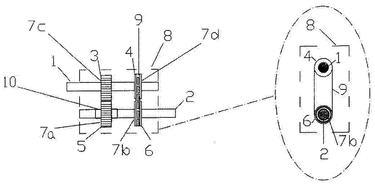
[0021] Example Description ( figure 1 )

[0022] This example shows the most basic way of forming an object. This consists of constructing the coupling unit by a hybrid connection between the two shafts 1 , 2 without using a rotary inverter.

[0023] From the input shaft 1 to the output shaft 2 are placed transmission devices 3 and 5 and transmission devices 4 , 9 and 6 .

[0024] For further details on this embodiment: two elements are placed in the input shaft 1 suitable for transmitting the motion occurring in said shaft 1, in this case the cog 3 or gear, and at the minimum required distance A pulley or another cog or pinion 4 is located on the input shaft 1 .

[0025] A cog 5 and another cog with pinion 6 are placed on the output shaft 2 to which a rotary or one-way drive is coupled, in this case by two free wheels 7a and 7b Institutional composition. These unidirectional rotary or drive mechanisms 7a and 7b are placed so that they both exert a force on the shaft on w...


PUM


Abstract

The present invention relates to devices, transmissions and universal mechanical couplings (D.T.A.M.U.) with forces of different magnitudes and directions. The invention relates to a device, a transmission and a universal mechanical coupling, which make it possible to convert rotational forces of different magnitudes and directions applied to the same rotary shaft (1) and obtain a unidirectional movement in the output rotary shaft (2) As possible, the output rotary shaft (2) can be used in any medium. The device consists of an input shaft (1), an output shaft (2) and two devices (3 and 5) and (4, 9 and 6) for connecting said two shafts (1 and 2), the two Each of the shafts (1 and 2) has at least one one-way coupling (7a, 7b) and, in its most basic form, is not provided with a rotary inverter (15a).

Description

[0001] purpose of invention [0002] The purpose of the present invention is to couple rotational forces of different magnitudes and directions on the same rotational shaft, and obtain unidirectional motion on the output shaft. technical field [0003] The main field of application of this patent is the electrical industry, but it is closely related to the mechanical industry. It must be considered that its uses are varied. For example, it can be used as a converter to convert linear motion into rotary motion. Background technique [0004] There are various patent applications, several patent specifications for inventions, and several utility models that use drive trains to couple bidirectional motion in order to obtain unidirectional motion on an output shaft. For example, it is used to convert different directions of motion in which wave energy may flow. [0005] Among these patent applications can be found the patent WO2009101085A2 which discloses a device for converti...

Claims


Application Information

Patent Timeline
Patent Type & Authority Patents(China)
IPC IPC(8): F16H31/00
CPCF03B13/14F03B13/142F03B13/22F05B2260/4022F05B2260/4031F16H3/003Y02E10/30F16H31/00F16H3/10F16H37/02
Inventor 马可·安东尼奥·罗德里格斯·拉米雷斯
Owner 马可安东尼奥罗德里格斯拉米雷斯
Why Eureka
Try Eureka