Motor-car propelling type ejector

A catapult, propulsion technology, applied in the direction of launch/drag transmission, etc., can solve the problems of difficult control, pressure drop, and high manufacturing cost

Inactive Publication Date: 2017-03-08
柳峰
View PDF0 Cites 0 Cited by
  • Summary
  • Abstract
  • Description
  • Claims
  • Application Information

AI Technical Summary

Problems solved by technology

The biggest technical problem is how to prevent leaks from causing pressure drops
Although the existing electromagnetic catapult technology is superior to the steam catapult, the manufacturing cost is high, the structure is complicated, and the control is difficult. In particular, the cooperation of high-current power storage equipment and permanent magnet materials is required to achieve the ejection effect.

Method used


Image

  • Motor-car propelling type ejector
  • Motor-car propelling type ejector
  • Motor-car propelling type ejector

Examples


Embodiment Construction

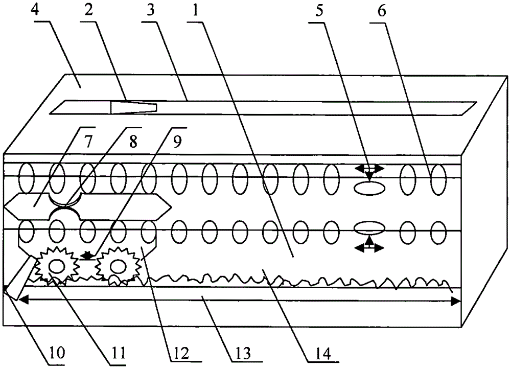
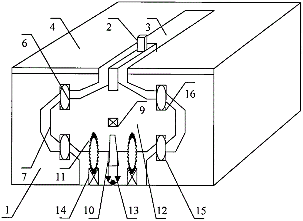
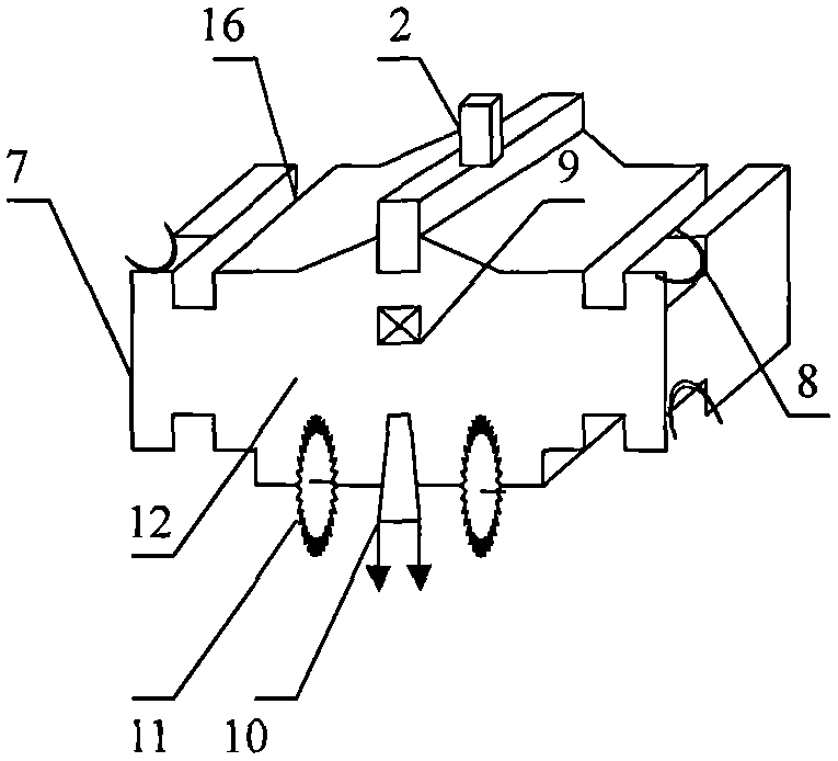
[0021] figure 1 As shown in the propulsion type catapult of a motor vehicle, an ejection chamber 1 is set in the hull, and two sets of sliding wheels 6 and brakes 5 are arranged in the ceiling and wall panels on both sides of the ejection chamber 1. The runway deck 4 is set, and the pulley groove 3 is set in the runway deck 4; two motor car tracks 14 with gear teeth are arranged on the bottom plate of the ejection chamber 1, and the horizontal lines of the teeth on the two motor car tracks 14 must be kept absolutely aligned with each other On a horizontal line, a motor car 12 is set on the motor car track 14, and a motor wheel 11 is arranged in the motor car 12: a sliding wing plate 7 is set on the motor car 12, and a brake hole 8 is set in the front and back of the sliding wing plate 7, and the sliding wing The plate 7 is arranged in the middle of the sliding wheel 6, the motor 9 is arranged in the motor car 12, the pantograph 10 is arranged at the rear end of the motor car 1...


PUM


Abstract

The invention provides a motor-car propelling type ejector. An ejection chamber (1) is disposed in a ship body; top plates and base plates on two sides inside the ejection chamber (1) are respectively provided with sliding wheels (6) and brake devices (5); a runway deck (4)is arranged on the top plates on two sides of the ejection chamber (1); a pulley slot (3) is formed in the runway deck (4); motor car tracks (14) with gear teeth are arranged on the base plates of the ejection chamber (1); a motor car (12) is arranged on the motor car tracks (14); motor car wheels (11) are arranged in the motor car (12); the motor car wheels (11) are arranged on the motor car tracks (14); the left and right sides of the motor car (12) are provided with slide wing plates (7); brake holes (8) are formed in the front and back surfaces of the slide wing plates (7); the slide wing plates (7) are arranged between sliding wheels (6); a motor (9) is disposed in the motor car (12); the back end of the motor car (12) is provided with a pantograph (10); a pulley trolley in the middle of the top end of the motor car (12) is provided with a tractor (2); and a power transmission network (13) is arranged in the base plate in the middle of the motor car track (14).

Description

technical field [0001] The invention relates to a motor vehicle propulsion type catapult, which relates to a catapult that can assist the aircraft to accelerate take-off when the carrier-borne aircraft on the national defense aircraft carrier takes off. Background technique: [0002] A motor vehicle propulsion type catapult of the present invention is designed and invented according to the basic principle of the existing motor vehicle and the working principle of the bearing. [0003] Although the steam catapult and electromagnetic catapult invented by the predecessors can make the carrier-based aircraft take off quickly, the difficulty of the structure of the steam catapult is to allow the driving piston / front guide structure to move freely in the cylinder gap and maintain Necessary work pressure. The biggest technical problem is how to prevent leaks from causing pressure drops. Although the existing electromagnetic catapult technology is superior to the steam catapult, t...

Claims


Application Information

Patent Timeline
Patent Type & Authority Applications(China)
IPC IPC(8): B64F1/06
Inventor 柳峰
Owner 柳峰
Why Eureka
Try Eureka