Eureka AIR delivers breakthrough ideas for toughest innovation challenges, trusted by R&D personnel around the world.

Universal mainframe case bracket device for operation of computer

A technology of bracket device and main box, which is applied in the direction of computer workstation table or platform, application, household appliances, etc., can solve the problems that cannot meet the positioning requirements of the main box, the main box is damp, and the movement is not convenient enough, so as to achieve easy replacement , prolong the service life and cushion the impact

Inactive Publication Date: 2017-03-22
孙丽君
View PDF5 Cites 24 Cited by
  • Summary
  • Abstract
  • Description
  • Claims
  • Application Information

AI Technical Summary

Problems solved by technology

[0002] Nowadays, computers have been widely used in many fields. Its fast calculation speed and convenient operation provide great convenience for people's work and entertainment. It has certain advantages in terms of flexibility and operational performance, so it is a model often used in office work. When operating a desktop computer, the main box is usually placed under the table, but it is easy to cause the main box to be damp if placed directly on the ground. Moreover, it is not convenient enough to move. Now, in order to meet the placement requirements of the main chassis, some main chassis brackets have appeared. However, although the currently used main chassis brackets can move flexibly, they cannot meet the positioning requirements of the main chassis. A bracket device that is more realistic and meets the needs of the main chassis is needed to solve the above problems

Method used


Image

  • Universal mainframe case bracket device for operation of computer
  • Universal mainframe case bracket device for operation of computer
  • Universal mainframe case bracket device for operation of computer

Examples


Embodiment Construction

[0019] The following will clearly and completely describe the technical solutions in the embodiments of the present invention with reference to the accompanying drawings in the embodiments of the present invention. Obviously, the described embodiments are only some, not all, embodiments of the present invention. Based on the embodiments of the present invention, all other embodiments obtained by persons of ordinary skill in the art without making creative efforts belong to the protection scope of the present invention.

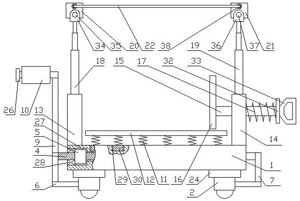
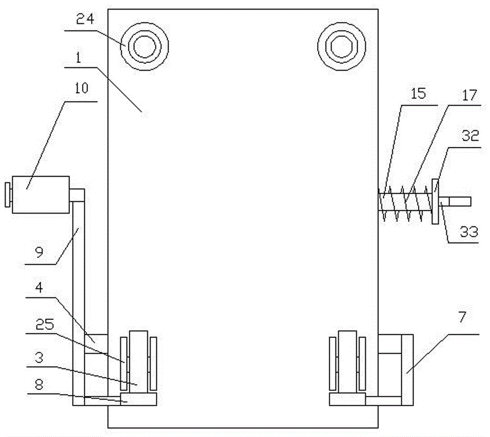
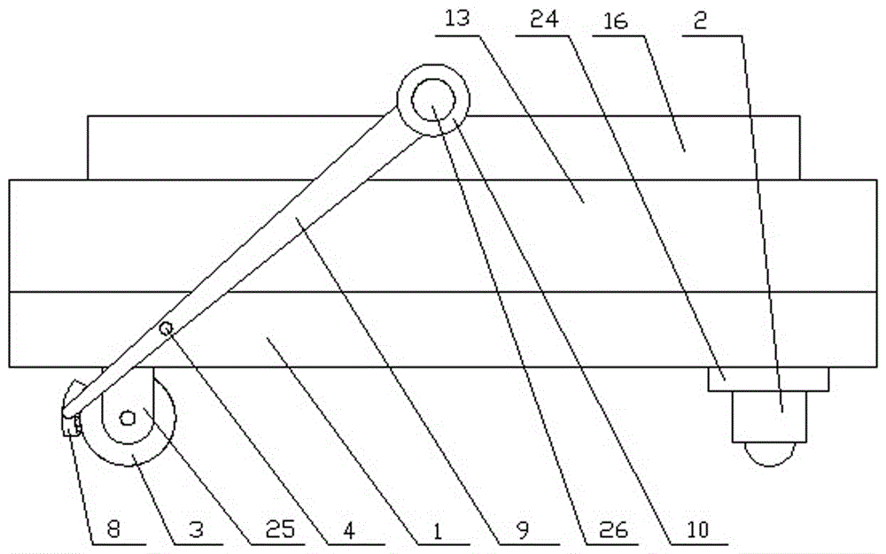
[0020] see Figure 1-5 , the present invention provides a technical solution: a universal mainframe bracket device for computer operation, including a device base 1, a set of universal wheels 2 and a set of rear wheels 3 are arranged on the lower part of the device base 1, and the device base 1 is equipped with a brake shaft 4, the brake shaft 4 rotates with the device base 1 through a coil spring 5, and the two ends of the brake shaft 4 are respectively provi...


PUM


Abstract

The invention discloses a universal mainframe case bracket device for operation of a computer. The universal mainframe case bracket device comprises a device base; a brake axle is arranged on the device base in a penetrating mode; the brake axle is rotationally matched with the device base through a coil spring; a left brake rod and a right brake rod are disposed at the two ends of the brake axle correspondingly; the left brake rod is integrated with a rotary rod; a left side frame and a right side frame are disposed on the two sides of the device base correspondingly; a movable rod is connected to the right side frame in a threaded mode; a clamping plate is disposed at one end of the movable rod; a left lifting rod and a right lifting rod are disposed on the upper portions of the left side frame and the right side frame correspondingly; the top of the left lifting rod is connected with a left top frame; the top of the right lifting rod is connected with a right top frame; and the left top frame and the right top frame are matched with dust-proof cloth. The universal mainframe case bracket device for operation of the computer is quite convenient to move and position and easy to operate, can provide good fixing and shock absorption conditions for a mainframe case and prevent dust from falling on the top of the mainframe case and achieves humanized design.

Description

technical field [0001] The invention relates to the field of computer auxiliary devices, in particular to a universal mainframe chassis bracket device for computer operations. Background technique [0002] Nowadays, computers have been widely used in many fields. Its fast calculation speed and convenient operation provide great convenience for people's work and entertainment. It has certain advantages in terms of flexibility and operational performance, so it is a model often used in office work. When operating a desktop computer, the main box is usually placed under the table, but it is easy to cause the main box to be damp if placed directly on the ground. Moreover, it is not convenient enough to move. Now, in order to meet the placement requirements of the main chassis, some main chassis brackets have appeared. However, although the currently used main chassis brackets can move flexibly, they cannot meet the positioning requirements of the main chassis. A bracket device ...

Claims


Application Information

Patent Timeline
Patent Type & Authority Applications(China)
IPC IPC(8): A47B21/00A47B21/04
CPCA47B21/00A47B21/04
Inventor 王永妍
Owner 孙丽君
Why Eureka
Eureka Blog
Learn More