
A mechanical seal

A technology of mechanical sealing device and sealing box, which is applied in the direction of engine sealing, mechanical equipment, engine components, etc., to achieve the effects of prolonging service life, convenient installation, and simple overall structure

Active Publication Date: 2018-01-12
天津市合润科技有限责任公司
View PDF8 Cites 0 Cited by
  • Summary
  • Abstract
  • Description
  • Claims
  • Application Information

AI Technical Summary

Problems solved by technology

[0007] In order to solve the technical problems existing in the known technology, the present invention provides a method for compensating the static ring of a large shaft diameter due to gravity to cause the problem of non-concentricity of the dynamic and static rings, and the uneven circumferential gap of the sealing ring between the static ring and the static ring seat. The problem of uneven distribution of friction force in the axial and circumferential direction ensures the stability and reliability of the user's equipment performance. At the same time, the elastic element can be adjusted and replaced arbitrarily without dismantling the overall device, so that the specific pressure of the sealing end face reaches the ideal design value. ; And effectively guarantee the concentricity and followability of the moving ring and the static ring mechanical seal device

Method used


Image

  • A mechanical seal
  • A mechanical seal
  • A mechanical seal

Examples


Embodiment Construction

[0040] In order to further understand the invention content, characteristics and effects of the present invention, the following examples are given, and detailed descriptions are as follows in conjunction with the accompanying drawings:

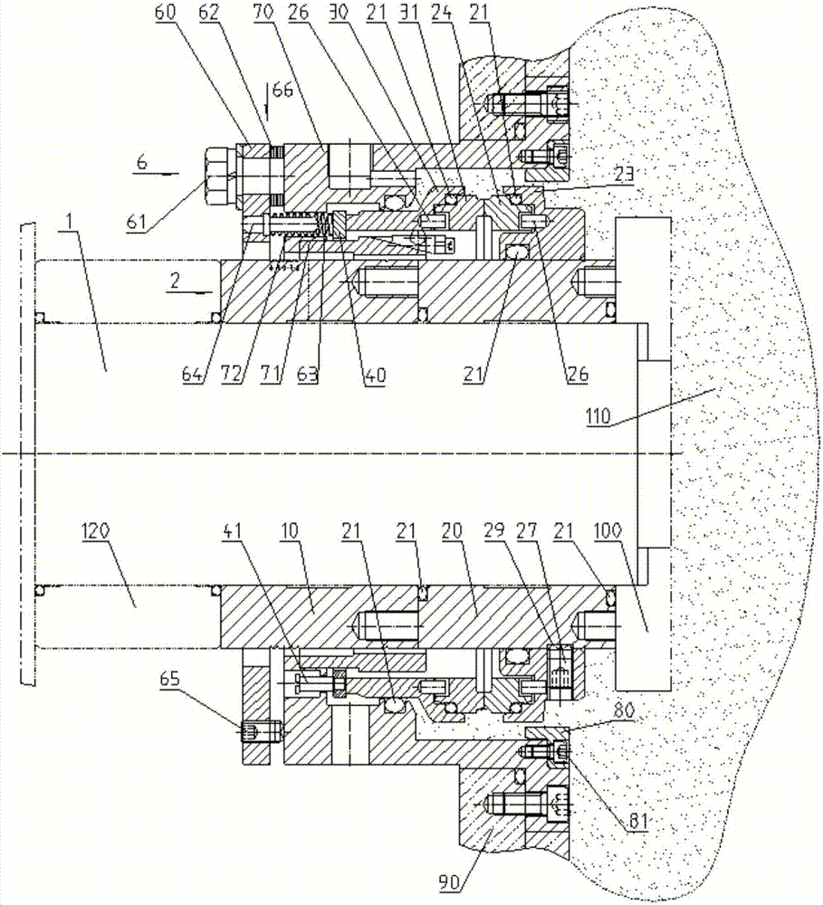
[0041] In this embodiment, the mechanical seal device used on the dredger pump of a large dredger is taken as an example for illustration, please refer to Figure 2 to Figure 7 , a mechanical seal device for a large-scale dredger dredger pump, the mechanical seal device is installed on the pump shaft 1 of the dredger inner dredger pump, and includes a seal box 70 sealingly connected with the dredger pump 90, and its main function is to make the whole set of machinery The static part of the seal is fixed with the mud pump 90, so that the static ring 31 is not rotated by the rotation of the moving ring 24; the shaft sleeve 2 installed on the shaft of the mud pump is located in the sealed box, and the function of the shaft sleeve is that the pump...


PUM


Abstract

The invention relates to a mechanical sealing device. The mechanical sealing device comprises a sealing box, a dynamic ring base with a dynamic ring and a static ring base with a static ring, wherein a pushing ring is arranged between the static ring base and the sealing box; the dynamic ring base is in fastening connection with a shaft sleeve through a fastening bolt, and the dynamic ring base and the shaft sleeve rotate together; a supporting space is reserved between the inner wall of the static ring base and the outer wall of the shaft sleeve; a static ring radial regulating mechanism which overcomes the problem that the static ring and the static ring base sink as a result of gravity is mounted in the supporting space; and an external adjustable type static ring axial compensating mechanism is arranged on the outer end surface of the sealing box. The mechanical sealing device solves the problem that the dynamic ring and the static ring are not concentric as a result of gravity of a large-shaft-diameter mechanical seal compensating static ring, and the problem that friction force in the circumferential axial direction is not uniformly distributed due to the fact that circumferential clearances of a seal ring between the static ring and the static ring base are not uniform, and the like; and meanwhile, the mechanical sealing device has the advantages that: for a split type mechanical seal and an integrated type mechanical seal, working strength, in a mounting using process, of a spring does not change due to regulation of a pump body, and in use, a damaged spring element can be timely replaced without dismounting equipment.

Description

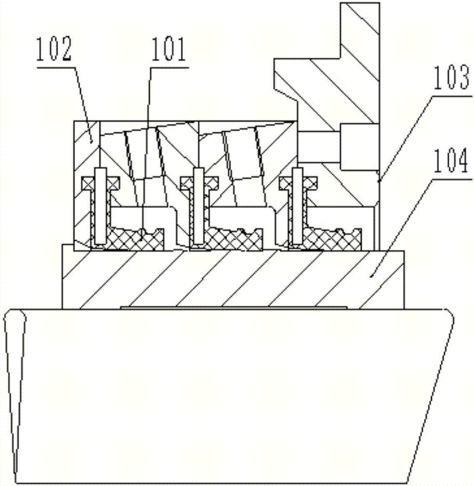
technical field [0001] The invention relates to the field of mechanical seals, more specifically, to a mechanical seal device. Background technique [0002] At present, the pump shaft sealing device of large dredgers at home and abroad adopts L-shaped rubber gasket sealing device. Its working principle is that three static L-shaped rubber gaskets 101 and the rotating shaft sleeve 104 dynamically rub against each other, and the pressure plate 102 is connected with the sealing chamber 103. , provide high-pressure clean water between the L-shaped rubber gasket seals to lubricate and block the pumped medium, use the elasticity of the rubber itself and the attached spring to provide wear compensation to achieve the purpose of sealing, see figure 1 . This kind of sealing device is suitable for a narrow range of working conditions, and its service life is unstable. The actual service life is mostly 1 to 6 months. It is affected by deflection, vibration, sharp particles and solid p...

Claims


Application Information

Patent Timeline
Patent Type & Authority Patents(China)
IPC IPC(8): F16J15/16F16J15/34
CPCF16J15/16F16J15/3472
Inventor 于建军
Owner 天津市合润科技有限责任公司
Learn More