
Hydraulic vibrating feeder

A hydraulic vibration and feeder technology, which is applied in vibrating conveyors, conveyors, transportation and packaging, etc., can solve the problems of inconsistent deformation of the rubber spring in the thickness direction, the influence of the stable operation of the feeder, and the inconsistency of the stiffness of the shearing rubber spring, etc.

Active Publication Date: 2020-07-03
河南辉强机械设备有限公司
View PDF7 Cites 0 Cited by
  • Summary
  • Abstract
  • Description
  • Claims
  • Application Information

AI Technical Summary

Problems solved by technology

However, in the existing structure of the vibration transmission body, the upper and lower shear rubber springs used are the same in size and performance, which makes the stiffness the same. After the equipment is installed, due to the heavy weight of the vibration transmission body itself, the vibration transmission In addition to the pre-tightening pressure in the thickness direction of the shear rubber spring installed at the lower part of the body, it is also subject to the pressure brought by the vibration transmission body's own weight, which leads to inconsistent deformation of the upper and lower shear rubber springs in the thickness direction. The rigidity of the upper and lower shear rubber springs is inconsistent, which causes the vibration direction of the feeder to drift and change during the working process, which seriously affects the stable operation of the feeder
[0010] Due to the above reasons, it is urgent to adopt a new technical solution to solve the problem of online adjustment and stable operation of the two-mass near-resonance inertial vibrating feeder in the case of large feeding volume.

Method used


Image

  • Hydraulic vibrating feeder
  • Hydraulic vibrating feeder

Examples


Embodiment Construction

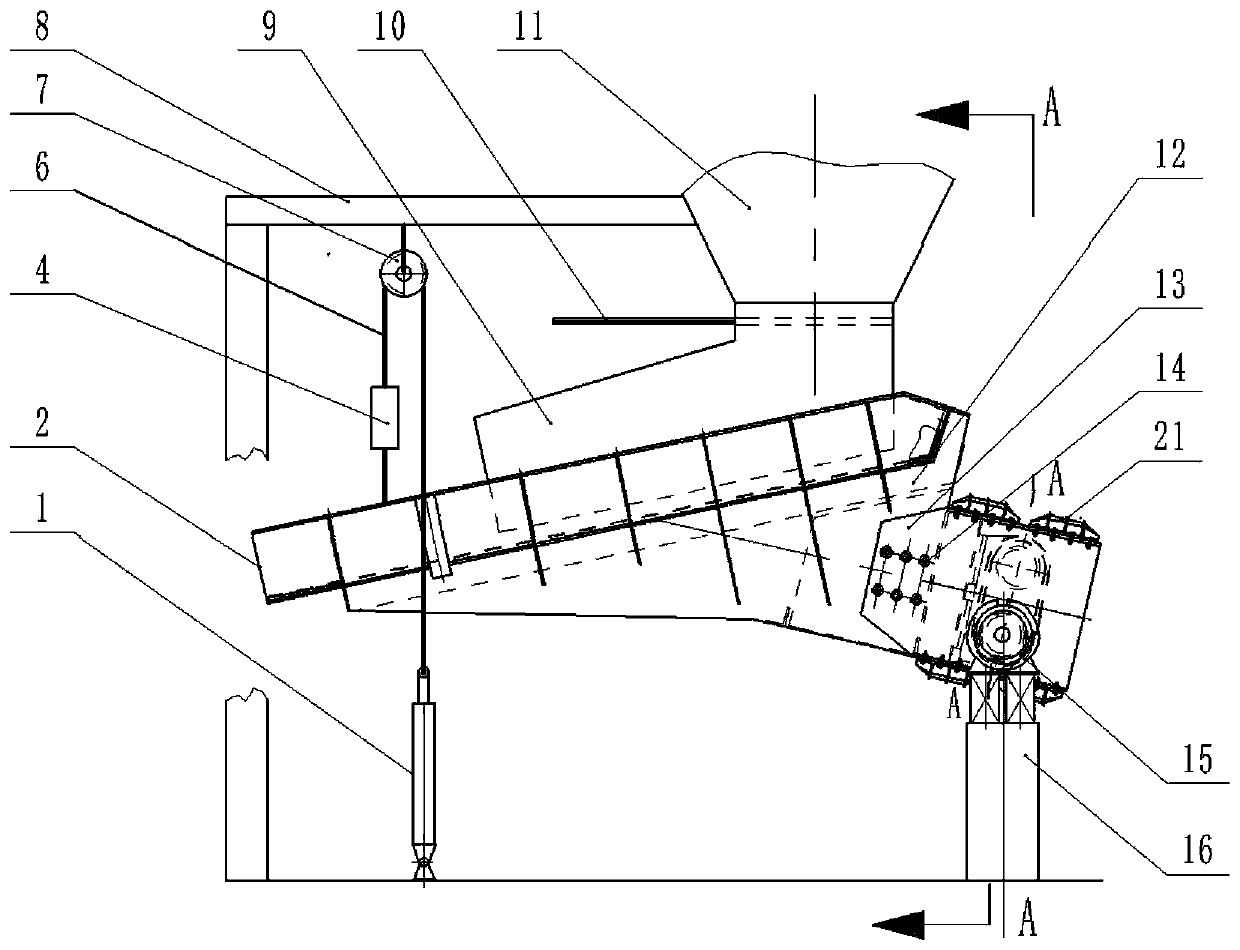
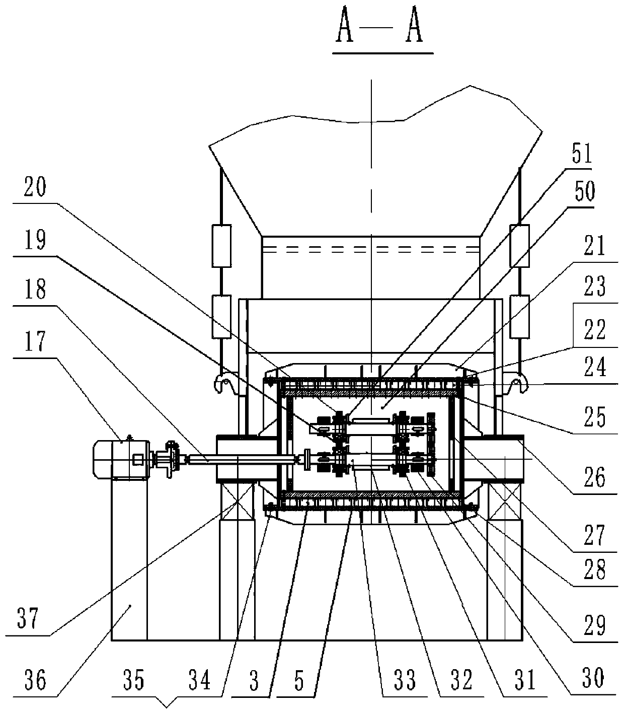
[0024] figure 1 and figure 2 The meanings of the serial numbers are as follows: 1. Rotary drive cylinder; 2. Vibration tank; 3. Lower shear rubber spring; 4. Damping spring; 5. Lower pressure plate; 6. Steel wire rope; 7. Pulley; 8. Foundation support; 9. Material guide trough; 10. Flat gate; 11. Material bin; 12. Connecting side plate; 13. Vibration transmission plate; 14. Connecting bolt; 15. Supporting spring sleeve frame; 16. Supporting spring support; Motor; 18. Universal joint coupling; 19. Bearing seat; 20. High-strength bolt; 21. Upper pressure plate; 22. Bolt; 23. Nut; 24. Upper shear rubber spring; 25. Upper connecting plate ;26, hollow tube; 27, side plate of vibration transmission body; 28, lower connecting plate of vibration transmission body; 29, gear; 30, eccentric block; 31, bearing; ; 35, coupling nut; 36, drive motor base; 37, support spring; 50, the rear bottom plate of the vibration transmission body;

[0025] In the embodiment, the vibrating tank body ...


PUM


Abstract

The invention relates to a hydraulic vibration feeder used for giving-out of materials in a bin, and belongs to the technical field of material conveying equipment. At present, a large number of double-mass near-resonance inertial vibration feeders are used in the metallurgy, mine, coal and other industries, and the problems that in the feeders, a vibration motor and a shearing rubber spring are prone to damage due to combustion under the large feeding amount, online feeding amount adjustment is not easy, and work is not stable exist. A pair of eccentric vibration exciters adopting gear engagement are arranged in a vibration transmission body, a coupler penetrating a hinged hollow pipe is used for connecting one eccentric vibration exciter with a drive motor, the original thickness of a shearing rubber spring at the upper portion of the vibration transmission body is smaller than that of a shearing rubber spring at the lower portion of the vibration transmission body, the radius of theinner circle of the hollow pipe is larger than or equal to 20 times of the work amplitude of the hydraulic vibration feeder, and the shock excitation force acting line generated by a pair of rotationshaft eccentric vibration exciters passes through the gravity center of a groove, it is guaranteed that the hydraulic vibration feeder effectively solves the above problems existing in the feeder, and obvious beneficial effects are achieved.

Description

technical field [0001] The invention relates to a hydraulic vibrating feeder for feeding materials in a silo, and belongs to the technical field of material conveying equipment. Background technique [0002] At present, two-mass near-resonance inertial vibrating feeders are widely used in metallurgy, mining, coal and other industries. This kind of feeder has the advantages of low power consumption and large feeding volume, so it has been used in actual production to a certain extent. However, due to the limited structure of this kind of feeder, it is impossible to adjust the feeding amount of the feeder in real time during the operation of the equipment. Angle or by adjusting the vibration frequency of the vibrator or vibration motor, but the existing structure can not adjust the vibration angle of the tank in real time, because if the vibration frequency is adjusted, it will affect the resonance of the vibrating feeder The working state cannot be realized in practical appl...

Claims


Application Information

Patent Timeline
Patent Type & Authority Patents(China)
IPC IPC(8): B65G27/20B65G27/08B65G27/22
CPCB65G27/08B65G27/20B65G27/22B65G2201/04B65G2201/045
Inventor 吴振卿郭建军文天亮史来领郭建菊
Owner 河南辉强机械设备有限公司
Learn More