Right angle connector with terminal contact protection

A connector, connector assembly technology, applied in the direction of vehicle connectors, devices for connecting, engaging/disconnecting components, etc.

Active Publication Date: 2017-03-22
APTIV TECH LTD
View PDF6 Cites 8 Cited by
  • Summary
  • Abstract
  • Description
  • Claims
  • Application Information

AI Technical Summary

Problems solved by technology

However, additional protection against accidental contact with e

Method used


Image

  • Right angle connector with terminal contact protection
  • Right angle connector with terminal contact protection
  • Right angle connector with terminal contact protection

Examples


Embodiment Construction

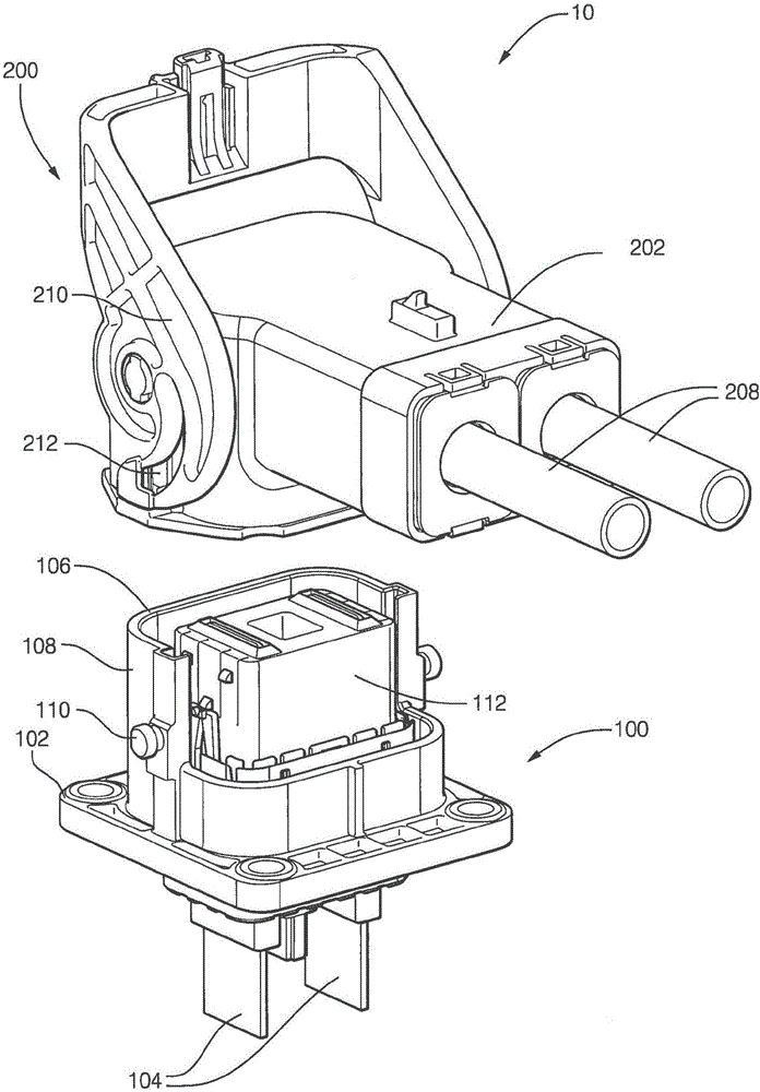
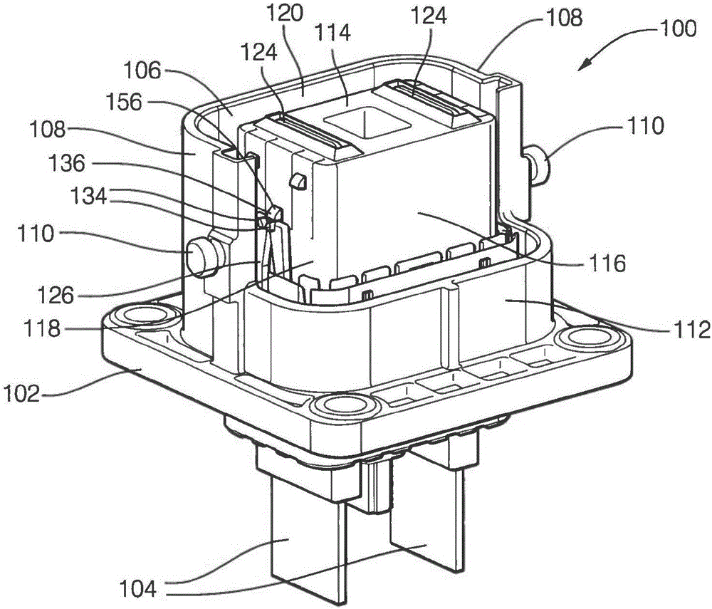
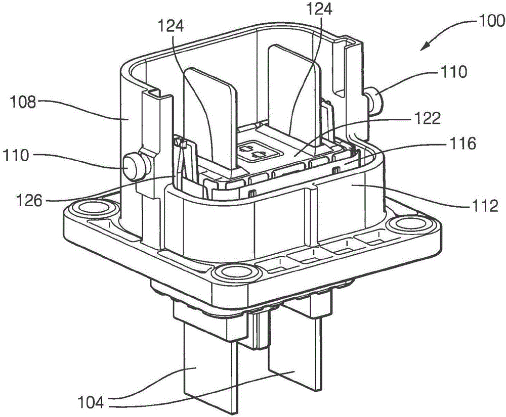
[0035] Presented herein is a connector system having a first connector and a second connector, each connector containing terminal elements or "terminals" for electrical wire cables, fiber optic cables, pneumatic lines, hydraulic lines, and the like. The housing of the first connector includes a movable terminal protection device (TPD). When the first connector is connected to the second connector, the TPD moves from a first position in which the terminals in the first connector are protected by the TPD to a second position in which a portion of the terminals protrudes through the TPD. The TPD remains in the first position until released by the second connector during connection of the first connector and the second connector. When the first and second connectors are disconnected, the second connector pulls the TPD from the second position back to the first position, thereby re-establishing protection of the terminals.

[0036] figure 1 In a non-limiting example of the connec...


PUM


Abstract

A connector assembly (10), such as a high voltage electrical connector assembly, includes a first connector (100) having a first housing (102) and an intermediate housing (112) attached to the first housing (102). The intermediate housing (112) is moveable from a first position (120) to a second position (122). A flexible retaining arm is configured to hold the intermediate housing (112) in the first position (120). The connector assembly (10) further includes a second connector (200) having a second housing (202). The second housing (202) defines a release wedge (214) that engages and flexes the retaining arm, thereby releasing the intermediate housing (112) from engagement with the retaining arm and allowing the intermediate housing (112) to move from the first position (120) to the second position (122) as the first connector (100) is connected to the second connector (200). A terminal in the first housing (102) is enclosed within the intermediate housing (112) in the first position (120), and protrudes from an aperture in a surface of the intermediate housing (112) in the second position (122).

Description

[0001] Cross References to Related Applications [0002] This application claims the benefit of priority to US Patent Application No. 14 / 815,223, filed September 11, 2015, the entire contents of which are incorporated herein by reference. technical field [0003] The present invention relates to connectors, and more particularly to connectors configured to prevent inadvertent contact with terminals. Background technique [0004] When the connector system is used in high voltage (greater than 48 volts) applications, such as electric vehicles, it is desirable to eliminate inadvertent contact with exposed energized electrical terminals. The opportunity for contact with terminals is most likely to occur when an operator is connecting and disconnecting mating connectors of a high voltage connection system. These connector systems typically use male blade terminals to accommodate the required current carrying capacity. The male blade terminals are received by corresponding femal...

Claims


Application Information

Patent Timeline
IPC IPC(8): H01R13/502H01R13/629
CPCH01R13/502H01R13/629H01R13/4538H01R2201/26H01R13/64H01R13/514H01R13/62H01R13/4534H01R13/62977
Inventor R·桑达拉克里什纳马切拉A·拉斯奇拉D·E·比宗
Owner APTIV TECH LTD
Why Eureka
Try Eureka