Robot movement locus key point error measurement method

A technology of robot motion and motion error, which is applied to measuring devices, instruments, and optical devices, etc., can solve problems such as narrow application fields, and achieve the effects of convenient control, easy implementation, and easy real-time acquisition.

Active Publication Date: 2017-03-29
TONGJI UNIV
View PDF5 Cites 18 Cited by
  • Summary
  • Abstract
  • Description
  • Claims
  • Application Information

AI Technical Summary

Problems solved by technology

The device of this invention can only detect the motion error of the robot trajectory on the plane, and the application field is relatively narrow

Method used


Image

  • Robot movement locus key point error measurement method
  • Robot movement locus key point error measurement method
  • Robot movement locus key point error measurement method

Examples


Embodiment 1

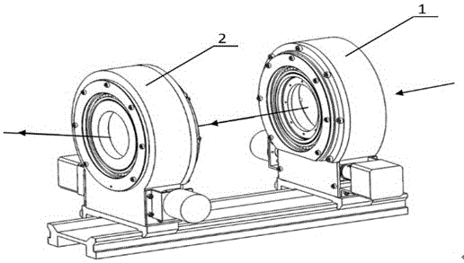
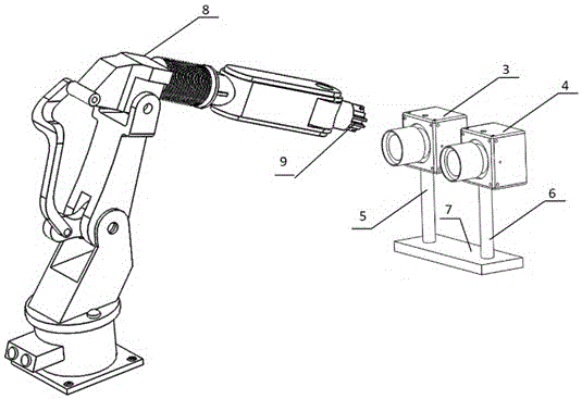
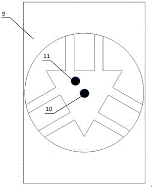
[0040] 2. The present invention provides a method for measuring the key point error of the robot motion track, which can realize the measurement of the key point motion error during the robot motion process: during the robot motion process, the robot is controlled to stop at a certain key point, and the visual imaging system At this time, the coordinates of the actual space point at the end of the robot are collected, and the dual prism tracking device generated by the key point generates the coordinates of the theoretical space point. By calculating the distance between the two points, the robot motion error at the key point can be obtained. The object of the present invention is achieved through the following parts: a dual prism tracking device including key point generation and a binocular vision measurement system for key point image acquisition. According to the position coordinates of key points in the trajectory of the robot, the rotating double prism produces a high-pre...


PUM


Abstract

The invention relates to a robot movement locus key point error measurement method. According to the method, key discrete point motion error measurement in a robot movement process can be realized, in the robot movement process, a robot is controlled for stopping movement at a certain key point, a tail end actual space point coordinate of the robot at present is acquired through a vision imaging system, a double-prism tracking device generated at the key point generates a theory coordinate of the key point to which place the robot moves, through comparing and calculating the distance between the two points, a robot movement error at a key discrete point can be acquired. The method belongs to a non-contact measurement robot movement locus error method, direct contact with the robot is not required, and movement locus key point error measurement of the robot can be accurately carried out on the condition that no damage to the robot is guaranteed.

Description

technical field [0001] The invention relates to a method for measuring the error of a key point in a robot motion track, in particular to a method for measuring the error of a key point of a robot motion track by combining a double prism tracking device for key point generation and a visual measurement system. Background technique [0002] Prior technology (Mechanical Science and Technology, Issue 2, 2011, Volume 20, Page 252, Qian Ruiming "Research on Dynamic Error Integrated Laser Measurement and Compensation of Flexible Robots") proposes a method based on 3 laser generators and 3 lasers The dynamic error measurement method of the flexible member of the position detector (PSD), the method can measure five deformation components except the rod length direction, and the optical path and measurement model are simple; the position of the light point on the PSD and the error components of the member and The relationship between the dynamic errors of the robot end effector and i...

Claims


Application Information

Patent Timeline
Patent Type & Authority Applications(China)
IPC IPC(8): G01B11/00
CPCG01B11/002
Inventor 李安虎左其友
Owner TONGJI UNIV
Why Eureka
Try Eureka