Coded lock valve structure
A combination lock and valve technology, applied in the direction of valve lift, valve details, valve device, etc., can solve the problems of troublesome operation, poor safety of limited filling, etc., and achieve the effect of high safety and simple operation
- Summary
- Abstract
- Description
- Claims
- Application Information
AI Technical Summary
Problems solved by technology
Method used
Image
Examples
Embodiment 1
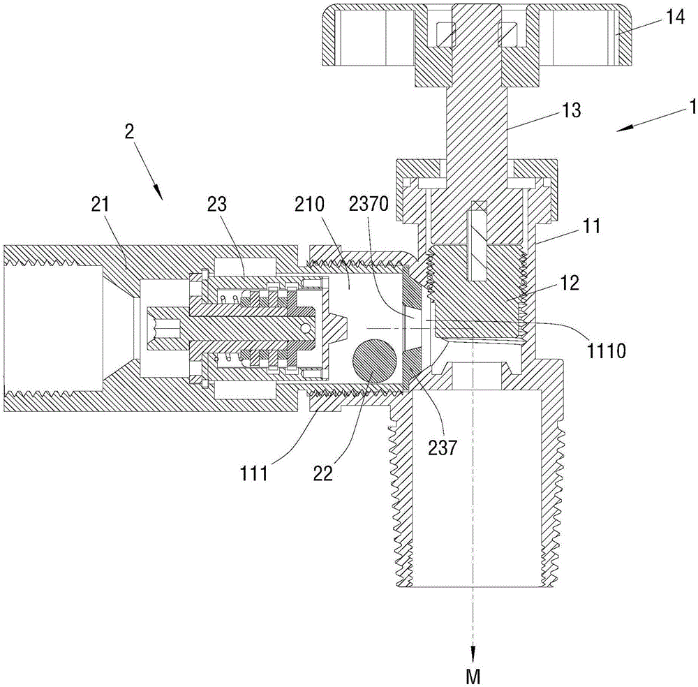
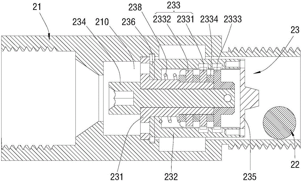
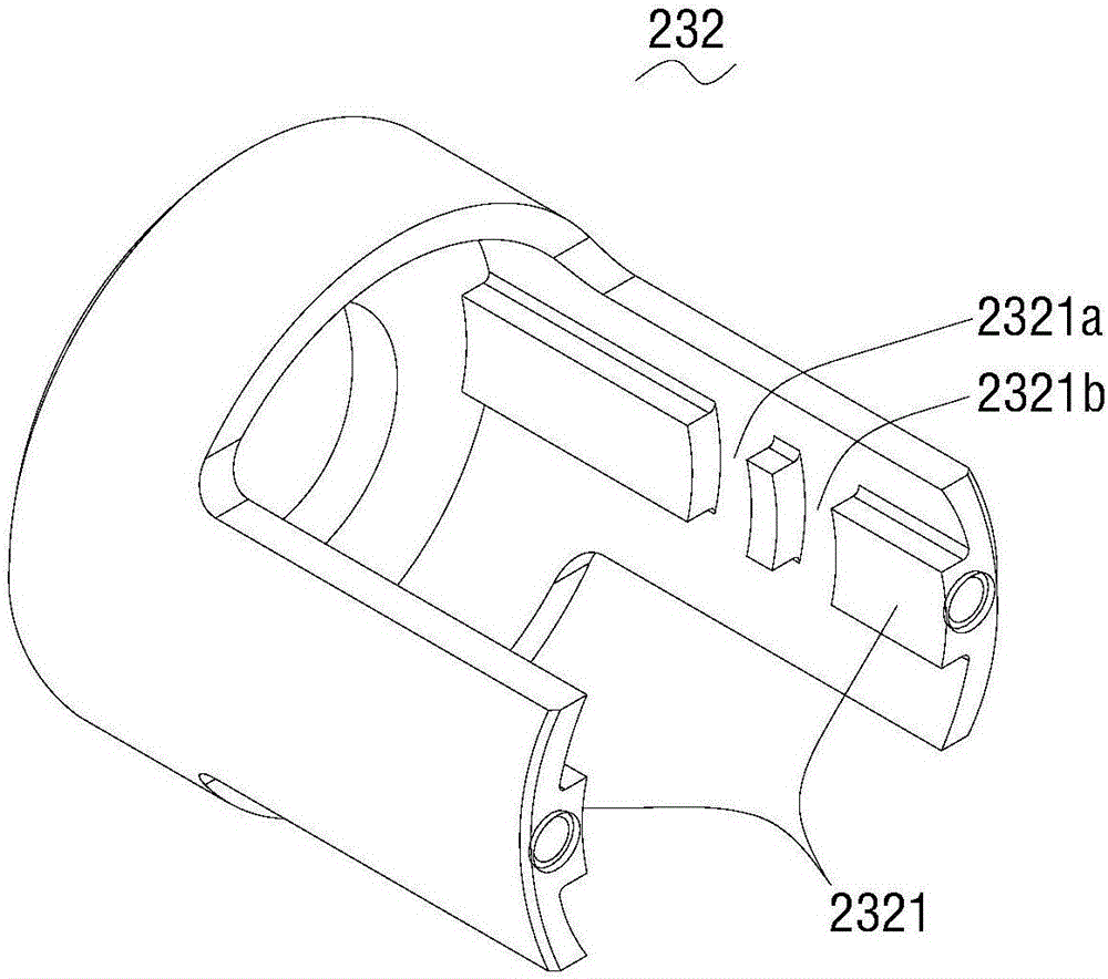
[0037] Such as Figure 1 to Figure 12 As shown, the outer wall of the valve body 11 has a side connection portion 111 that can be connected to an air gun, and the inner end of the side connection portion 111 has an air inlet and outlet port 1110 communicating with the air channel M. The combination lock valve structure includes a combination lock assembly 2 that can control the opening or closing of the air inlet and outlet 1110 to control the opening and closing of the airway M. The combination lock assembly 2 is connected to the side portion 111 of the valve body 11 . Specifically, the combination lock assembly 2 may include a fixed cylinder 21, a sealing ball 22 and a combination lock 23. One end of the fixed cylinder 21 extends into the side connection portion 111 of the valve body 11 to form a fixed connection and communication. The combination lock 23 is arranged on the fixed cylinder 21. Between the side connection part 111, here, the fixed cylinder 21 has an inner cavi...
Embodiment 2
[0056] Such as Figure 13 As shown, the bottom end of the above-mentioned valve body 11 has an extension part 112 that can be connected with a gas cylinder (liquefied gas cylinder, oxygen gas cylinder, etc.), and the extension part 112 communicates with the above-mentioned air passage M, and the above-mentioned combination lock assembly 2 is arranged on the inside the extension 112 . Specifically, one end of the above-mentioned fixed cylinder 21 protrudes into the extension part 112 to form a fixed connection and communication. 23 is specifically located in the extension portion 112, and the sealing ball 22 is located in the fixed cylinder 21; here, the fixed cylinder 21 is provided with a vent hole 2100 communicating with the air passage M, and the sealing ball 22 can block the vent hole 2100 under the action of the fluid. Obstructing the airway M is achieved.
[0057] Such as Figure 13 with Figure 14 As shown, in this embodiment, the combination lock 23 may include a c...
PUM
 Abstract
Description
Claims
Application Information
 - R&D
- Intellectual Property
- Life Sciences
- Materials
- Tech Scout
- Unparalleled Data Quality
- Higher Quality Content
- 60% Fewer Hallucinations
Browse by: Latest US Patents, China's latest patents, Technical Efficacy Thesaurus, Application Domain, Technology Topic, Popular Technical Reports.
© 2025 PatSnap. All rights reserved.Legal|Privacy policy|Modern Slavery Act Transparency Statement|Sitemap|About US| Contact US: help@patsnap.com


