
Valve structure provided with coded lock

A combination lock and valve technology, applied in the direction of valve lift, valve detail, valve device, etc., can solve the problems of poor safety and troublesome operation of limited filling, and achieve the effect of high safety and simple operation

Active Publication Date: 2017-05-10
SHENZHEN LANYANG TECH
View PDF7 Cites 3 Cited by
  • Summary
  • Abstract
  • Description
  • Claims
  • Application Information

AI Technical Summary

Problems solved by technology

[0004] The purpose of the present invention is to provide a coded lock valve structure, aiming to solve the problems in the prior art that the existing liquefied gas cylinder valves have limited filling safety and troublesome operation

Method used


Image

  • Valve structure provided with coded lock
  • Valve structure provided with coded lock
  • Valve structure provided with coded lock

Examples


Embodiment 1

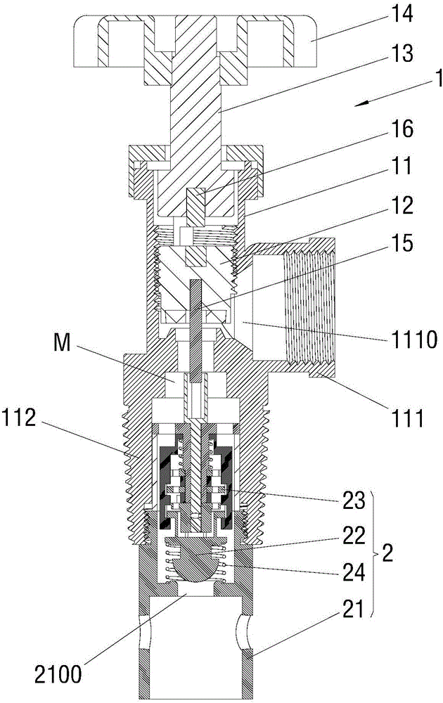
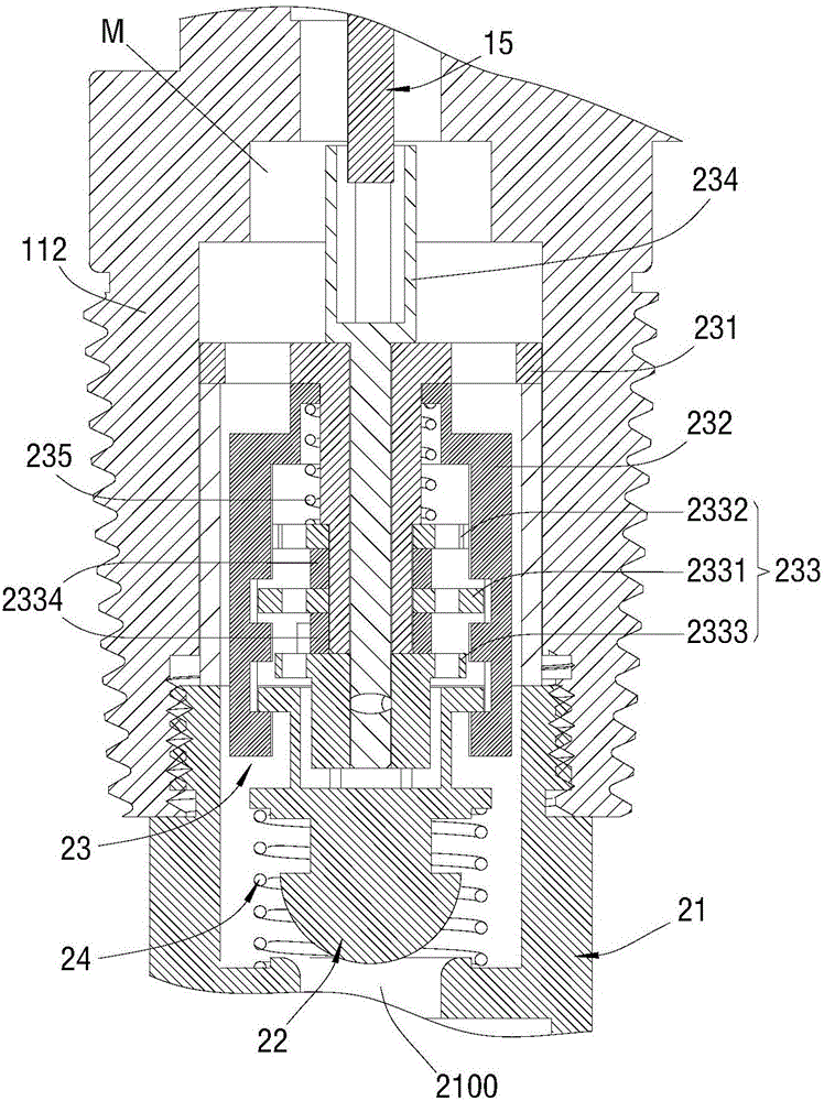
[0044] Such as Figure 1 to Figure 11 As shown, the bottom end of the valve body 11 has an extension 112 that can be connected to a gas cylinder (liquefied gas cylinder, oxygen cylinder, etc.), the extension 112 communicates with the air passage M, and the combination lock assembly 2 is arranged on the extension. Section 112. Specifically, one end of the above-mentioned fixed cylinder 21 extends into the extension portion 112 to form a fixed connection and communication. At the same time, the blocking body 22 and the combination lock 23 are arranged in the cavity formed by the connection between the fixed cylinder 21 and the extension portion 112. Here, the combination lock 23 is specifically located in the extension part 112, the blocking body 22 is located in the fixed cylinder 21, and the lower end of the fixed cylinder 21 can extend into the gas cylinder; Under the state that coded lock 23 is self-locked and blocking body 22 breaks away from this coded lock 23 or under th...

Embodiment 2

[0062] Such as Figure 12 with Figure 13 As shown, the outer wall of the valve body 11 has a side joint 111 that can be connected to an air gun, and the inner end of the side joint 111 has an air inlet and outlet 1110 that communicates with the air passage M and can be sealed and matched with the blocking body 22 . One end of the fixed cylinder 21 extends into the side connection portion 111 to form a fixed connection and communication, and the combination lock 23 is arranged between the fixed cylinder 21 and the side connection portion 111. Here, the fixed cylinder 21 has an inner cavity 210, and the combination lock 23 is specifically set in the lumen 210 . In this embodiment, when the combination lock 23 is self-locking and the blocking body 22 is out of the combination lock 23 or in the state where the combination lock 23 is unlocked and the blocking body 22 is locked, the blocking body 22 can be pushed by the filling fluid. Block the air inlet and outlet 1110 to block ...


PUM


Abstract

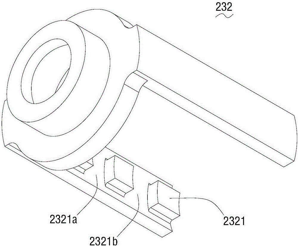
The invention relates to the technical field of valve structures and discloses a valve structure provided with a coded lock. The valve structure provided with the coded lock comprises a valve assembly. The valve assembly comprises a valve body provided with an air duct. A coded lock assembly which can control on-off of the air duct is arranged on the valve body. The coded lock assembly comprises a fixed cylinder which is connected with the valve body and communicates with the air duct, a blocking body which is arranged in the fixed cylinder and used for blocking the air duct, and the coded lock which is arranged between the fixed cylinder and the valve body and can limit movement of the locking body so as to remove blocking of the air duct by the locking body. By arranging the blocking body and the coded lock matched with the blocking body in a locking mode in the fixed cylinder, filling fluid can push the blocking body to block the air duct so as to limit filling in the state that the coded lock is self-locked and the locking body is separated from the coded lock or in the state that the coded lock is self-unlocked and the blocking body is locked; in addition, in the state that the coded lock is self-locked and the blocking body is locked, blocking of the air duct by the blocking body is removed, and thus filling purpose can be achieved; and the valve structure can limit filling, thereby being high in safety and easy to operate.

Description

technical field [0001] The invention relates to the technical field of valve structures, in particular to a combination lock valve structure. Background technique [0002] Liquefied petroleum gas, oxygen, hydrogen, carbon dioxide and other gases are commonly used in daily production and life, and these gases are generally flammable, high-pressure, and very dangerous. Some gases cannot be mixed with other gases, otherwise it will cause serious safety accidents. For example, if hydrogen is filled in an oxygen cylinder, it will cause an explosion during use. Liquefied petroleum gas occupies a large market share in China because of its cleanliness and environmental protection. However, due to its high risk, the accident rate is still high, and because it is used in public places, once an accident occurs, it will cause great harm. [0003] At present, liquefied petroleum gas is filled at fixed points according to safety regulations, but due to various reasons, cross-filling is v...

Claims


Application Information

Patent Timeline
IPC IPC(8): F16K35/08F16K1/14
CPCF16K1/14F16K35/08
Inventor 李涛
Owner SHENZHEN LANYANG TECH
Learn More