Coiling and positioning device of steel band

A technology of circular positioning and steel strip, applied in the field of rolling circle positioning device of steel strip, can solve the problems of complicated operation and low processing efficiency, etc.

Active Publication Date: 2017-04-26
WUXI KAIHAN TECH
View PDF6 Cites 0 Cited by
  • Summary
  • Abstract
  • Description
  • Claims
  • Application Information

AI Technical Summary

Problems solved by technology

In the existing steel strip processing system, the steel strip must be unloaded from the rolling equipment after the second rounding, and then positioned and installed on the positioning tool. The operation is cumbersome and the processing efficiency is low.

Method used


Image

  • Coiling and positioning device of steel band
  • Coiling and positioning device of steel band
  • Coiling and positioning device of steel band

Examples


Embodiment Construction

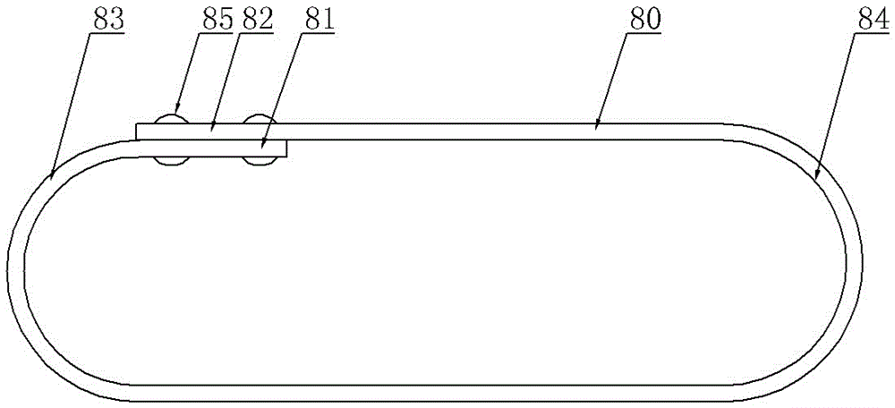
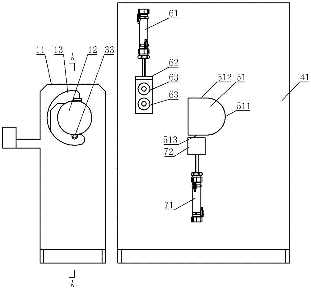
[0018] like Figure 2~Figure 4 As shown, it includes a first support frame 11 and a second support frame 41, the first support frame 11 is provided with a first simulation block 12 and a rolling mechanism, the second support frame is provided with a second simulation block, a steel belt lifting Mechanism and steel belt pressing mechanism;

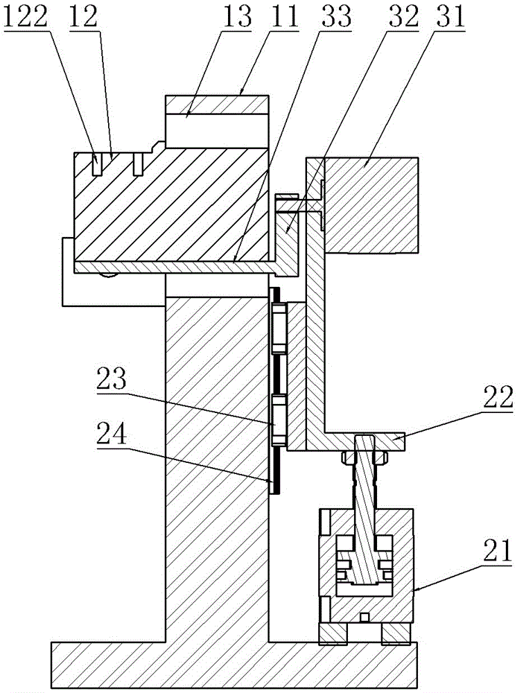
[0019] The first simulation block 12 is vertically fixed on the first support frame 11, and the side surface of the first simulation block 12 perpendicular to the first support frame 11 is composed of an arc-shaped curved surface 123 and a first plane 121 connecting the top two ends of the arc-shaped curved surface, The first support frame 11 is provided with an arc-shaped through groove 13 at the outer part of the side surface;

[0020] Rolling mechanism comprises servomotor 31, connecting rod 32 and depression bar 33, and the two ends of connecting rod 32 are respectively fixedly connected the rotating shaft of servomotor 31 and depressi...


PUM


Abstract

The invention provides a coiling and positioning device of a steel band, which has the advantages of simplicity and convenience in operation and high processing efficiency. The coiling and positioning device comprises a first support frame and a second support frame, wherein a first simulation block and a coiling mechanism are arranged on the first support frame, and a second simulation block, a steel band lifting mechanism and a steel band pressing mechanism are arranged on the second support frame; the first simulation block is vertically fixed to the first support frame, the side surface, which is perpendicular to the first support frame, of the first simulation block is formed by an arc-shaped curved surface and a first plane which is connected to both ends of the top of the arc-shaped curved surface, and an arc-shaped through groove is formed in a position in the outer side of the side surface of the first support frame; and the coiling mechanism comprises a servo motor, a connecting rod and a pressing rod, both ends of the connecting rod are fixedly connected with a rotating shaft of the servo motor and the pressing rod respectively, and the pressing rod penetrates through the arc-shaped through groove and can be driven to move along the arc-shaped through groove by the servo motor.

Description

technical field [0001] The invention relates to the field of production and processing of steel strips, in particular to a coiling positioning device for steel strips. Background technique [0002] A steel strip whose structure is as figure 1 As shown, the two ends 81, 82 of the steel strip 80 are respectively connected by the female and female rivets 85, and arc-shaped connecting parts 83, 84 are provided on both sides. The steel strip 80 is generally processed and formed through four processes of punching, rolling, positioning, and riveting. The rolling process is divided into a rolling process and a second rolling process. In the connection part 83, the positioning process positions the two ends 81 and 82 of the steel strip to fit together, and the riveting holes at the two ends coincide with each other. In the existing steel strip processing system, the steel strip must be unloaded from the rolling equipment after the second rounding, and then positioned and installed ...

Claims


Application Information

Patent Timeline
Patent Type & Authority Applications(China)
IPC IPC(8): B21D43/00B21D5/04
CPCB21D5/002B21D5/04
Inventor 姚舜雄
Owner WUXI KAIHAN TECH
Why Eureka
Try Eureka