
Rolling device for steel strip

A rolling device and steel belt technology, applied in the direction of feeding device, positioning device, storage device, etc., can solve the problems of inconvenient maintenance and complicated structure of the rolling device, and achieve the effect of convenient maintenance and simple structure

Active Publication Date: 2018-08-21
WUXI KAIHAN TECH
View PDF5 Cites 0 Cited by
  • Summary
  • Abstract
  • Description
  • Claims
  • Application Information

AI Technical Summary

Problems solved by technology

The steel strip 40 is generally formed through four processes of punching, rolling, positioning, and riveting. The rolling device used to realize the rolling operation has a complicated structure and is inconvenient to maintain.

Method used


Image

  • Rolling device for steel strip
  • Rolling device for steel strip
  • Rolling device for steel strip

Examples


Embodiment Construction

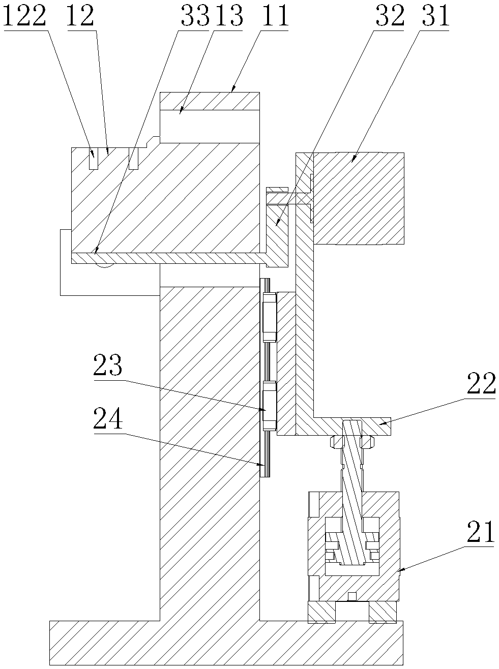
[0017] Such as Figure 3~Figure 4 As shown, it includes a support frame 11, a simulation block 12 and a rolling mechanism;

[0018] The simulation block 12 is vertically fixed on the support frame 11, the side of the simulation block 12 perpendicular to the support frame 11 is composed of an arc-shaped curved surface 123 and a plane 121 connecting the top two ends of the arc-shaped curved surface 123, and the support frame 11 is located at the outer side of the side surface. There is an arc-shaped slot 13 matching the arc-shaped curved surface 123 and the plane 121;

[0019] Rolling mechanism comprises servomotor 31, connecting rod 32 and depression bar 33, and the two ends of connecting rod 32 are respectively fixedly connected the rotating shaft of servomotor 31 and depression bar 33, and depression bar 33 runs through arc-shaped groove 13, and can be in servo Driven by the motor 31, it moves along the arc-shaped slot 13;

[0020] The device also includes a pressing mechan...


PUM


Abstract

The invention provides a steel band coiling device. The steel band coiling device can rapidly complete coiling operation and is simple in structure and convenient to maintain. The steel band coiling device comprises a supporting frame, a simulation block and a coiling mechanism, and is characterized in that the simulation block is vertically fixed to the supporting frame; the side face, perpendicular to the supporting frame, of the simulation block is composed of an arc surface and a plane connected with the two ends of the top of the arc surface; an arc penetrating groove matched with the arc surface and the plane is formed in the part, located outside the side face, of the supporting frame; and the coiling mechanism comprises a servo motor, a connecting rod and a pressing rod, the two ends of the connecting rod are fixedly connected with a rotary shaft of the servo motor and the pressing rod correspondingly, and the pressing rod penetrates through the arc penetrating groove and can be driven by the servo motor to move along the arc penetrating groove.

Description

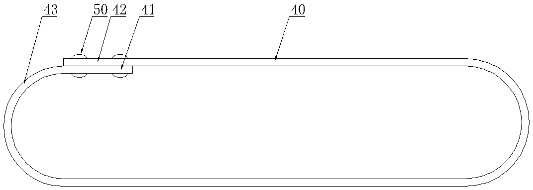
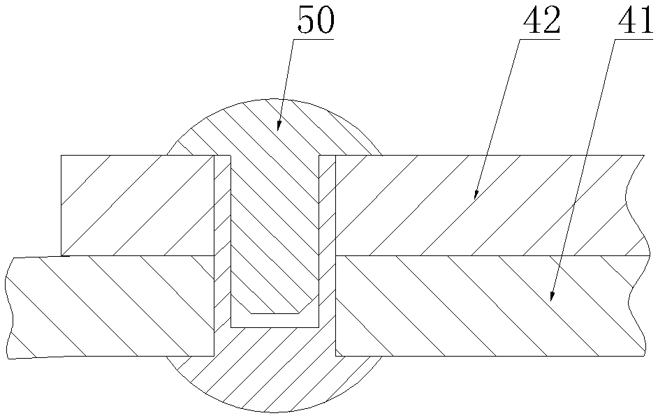
technical field [0001] The invention relates to the field of production and processing of steel strips, in particular to a rounding device for steel strips. Background technique [0002] A steel strip whose structure is as figure 1 , figure 2 As shown, the two ends 41 and 42 of the steel strip 40 are respectively connected by female and female rivets 50 , and arc-shaped connecting parts 43 are provided on both sides. The steel strip 40 is generally formed through four processes of punching, rolling, positioning, and riveting, and the rolling device for realizing the rolling operation has a complex structure and is inconvenient to maintain. Contents of the invention [0003] In view of the above problems, the present invention provides a rolling device for steel strips, which can quickly complete the rolling operation, and has a simple structure and convenient maintenance. [0004] Its technical scheme is such that it includes a support frame, a simulation block and a r...

Claims


Application Information

Patent Timeline
Patent Type & Authority Patents(China)
IPC IPC(8): B21D5/04B21D43/00
CPCB21D5/002B21D5/04
Inventor 姚舜雄
Owner WUXI KAIHAN TECH
Learn More