
Embedded junction box for buildings and construction method of embedded junction box

A technology for junction boxes and buildings, which is applied in the directions of buildings, building structures, cable installation devices, etc., can solve the problems of inconvenient installation and poor sealing effect of ordinary junction boxes, and achieve convenient installation, beautiful decoration effect, safety, The effect of saving construction time

Inactive Publication Date: 2017-04-26
CHINA MCC17 GRP
View PDF8 Cites 1 Cited by
  • Summary
  • Abstract
  • Description
  • Claims
  • Application Information

AI Technical Summary

Problems solved by technology

[0005] The technical problem to be solved by the present invention is: common junction box has poor sealing effect and inconvenient installation

Method used


Image

  • Embedded junction box for buildings and construction method of embedded junction box
  • Embedded junction box for buildings and construction method of embedded junction box
  • Embedded junction box for buildings and construction method of embedded junction box

Examples


Embodiment 1

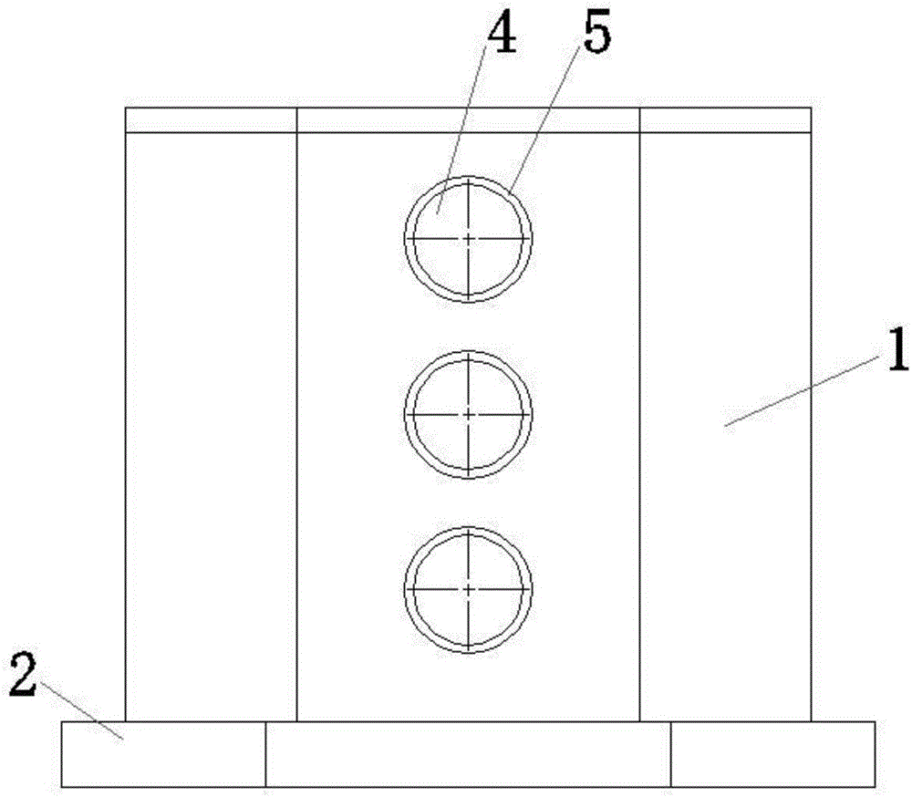
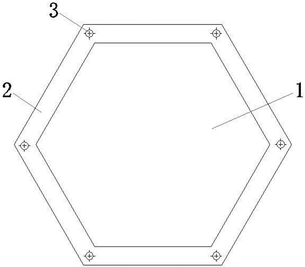
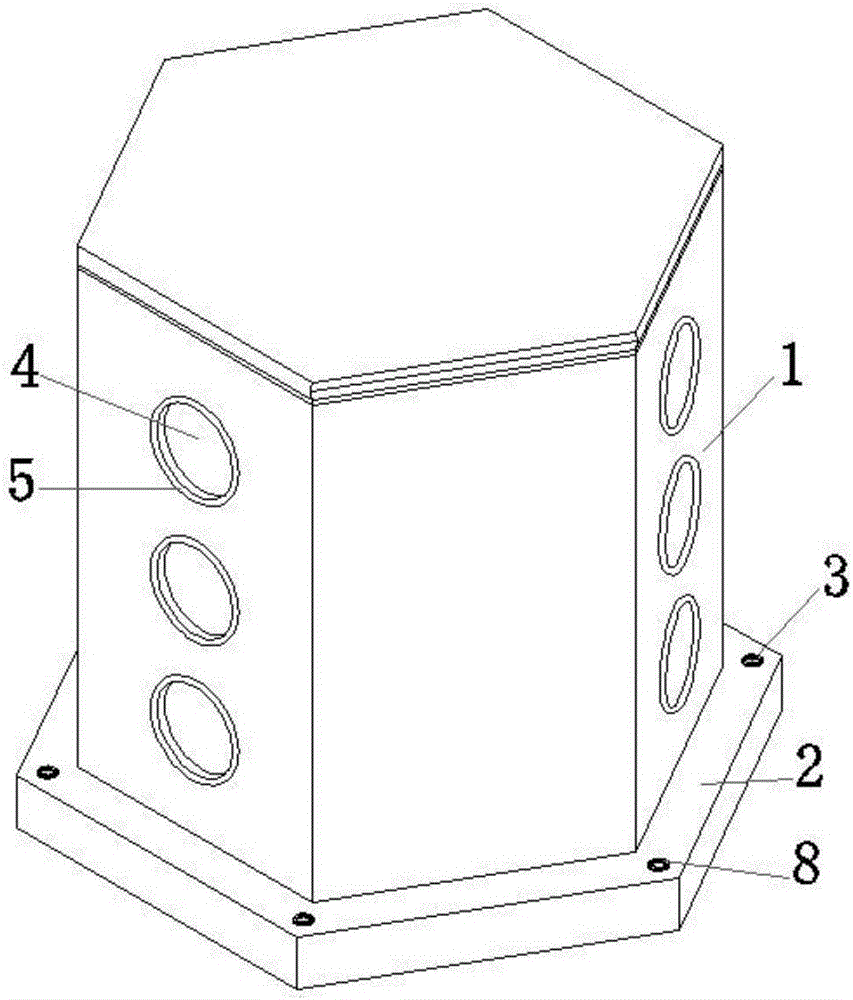
[0032] like Figure 1 to Figure 5 As shown, a pre-embedded junction box for construction is a hollow structure, which is characterized in that it includes a body 1, a base 2 and a head 7, the body 1 is a hollow structure with a regular polygonal horizontal section, and the top of the body 1 Sealing, one of the adjacent sides of the body 1 is provided with a threading hole 4, and an inwardly recessed gasket 5 is fixed on the threading hole 4; the base 2 is located directly below the body 1 and is fixedly connected to the body 1 As a whole, the base 2 is a hollow structure with a regular polygonal horizontal section, the side length of the regular polygon is longer than the side length of the regular polygon of the body 1, the base 2 is provided with a screw hole 3, and the screw hole 3 is located on the front At the corners of the polygon, the bottom surface of the base 2 is provided with a concave step 6 , and the sealing head 7 is bonded and adapted to the concave step 6 .

...

Embodiment 2

[0041] like Figure 1 to Figure 5 As shown, a construction method of a pre-embedded junction box for construction, the pre-embedded junction box has been filled with fillers such as sawdust before being sent to the construction site, and then the sealing head 7 is bonded to the bottom surface of the base 2, and the sealing gasket 5 All are inserted into the threading holes 4 and bonded tightly; the pre-embedded junction box has been inserted into the screw holes 3 before sending to the construction site. During the construction process, the cement nails are nailed to the corresponding positions of the formwork, and during the later decoration process, the operator only needs to open the head 7 to carry out line maintenance or installation work.


PUM


Abstract

The invention discloses an embedded junction box for buildings. The embedded junction box for buildings is of a hollow structure and comprises a body, a base and an end socket, wherein the body is of a hollow structure, the horizontal section of the body is a regular polygon, one of every two adjacent side faces of the body is provided with threading holes, inwards concave sealing pads are fixed to the threading holes, the base is of a hollow structure, the horizontal section of the base is a regular polygon, the base is provided with screw holes, a concave step is arranged on the bottom face of the base, and the end socket is matched with the concave step. In the construction process, the junction box can be arranged on the surface of a formwork through cement nails, the effect of firmness is improved, a traditional construction method that the junction box is fixed to the surface of the formwork after being tied with thin wires and iron nails is replaced, installation is more convenient, and the problem that the junction box is loosened and even disengaged from the formwork is solved. The inwards concave sealing pads are fixed to the threading holes, the end socket is bonded to and matched with the concave step, the two improvements remarkably improve the sealing effect of the junction box, and a traditional packaging method is replaced.

Description

technical field [0001] The invention belongs to the field of building construction, and in particular relates to a pre-embedded junction box for building and a construction method thereof. Background technique [0002] At present, in order to improve the decoration effect of housing construction projects, all the lines used for lighting and weak electricity will be hidden in the floor or wall. During the construction process, it is necessary to install threading pipes and junction boxes in the floor and wall in advance. [0003] The bottom surface of the ordinary junction box is an opening, but the junction box should be kept airtight after it is pre-embedded and before concrete pouring. For this reason, the inside of the junction box should be filled with sawdust. Void, if there is a gap, it will directly cause the concrete slurry to enter the junction box and block the threading pipe, which is not good for the later threading work or cannot be threaded; in the actual const...

Claims


Application Information

Patent Timeline
IPC IPC(8): E04F21/00H02G1/00
CPCE04F21/00H02G1/00
Inventor 张智忠刘生强高伟刚卢小军
Owner CHINA MCC17 GRP
Learn More