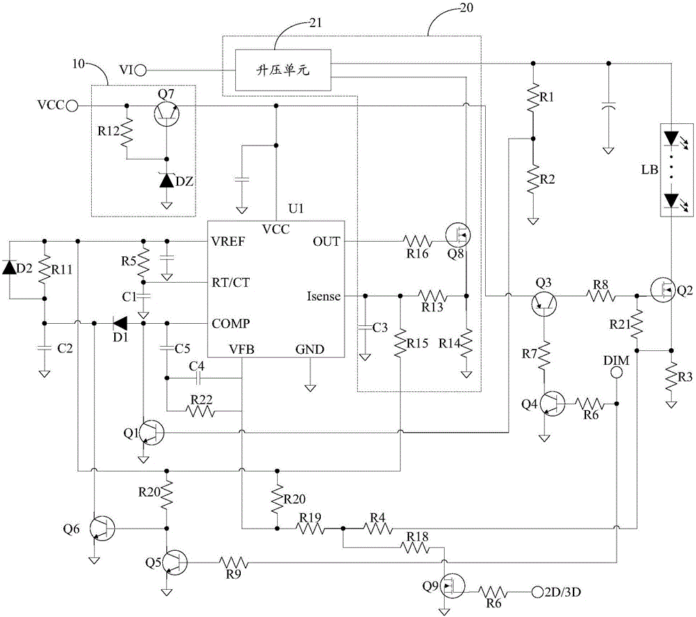
LED drive circuit

A LED drive and circuit technology, applied in electric light sources, electrical components, electroluminescent light sources, etc., can solve problems such as expensive, difficult to buy integrated circuits, and integrated circuits cannot be interchanged

Active Publication Date: 2017-04-26
SHENZHEN TCL DIGITAL TECH CO LTD
View PDF5 Cites 2 Cited by
  • Summary
  • Abstract
  • Description
  • Claims
  • Application Information

AI Technical Summary

Problems solved by technology

The LED backlight in LCD TVs is commonly used with BOOST circuits, and for the needs of dimming, the developed control integrated circuits are all dedicated, not only expensive, but also not universal, and the integrated circuits developed by various manufacturers cannot be interchanged. Once the IC is damaged, it is difficult to buy such a dedicated integrated circuit

Method used


Image

  • LED drive circuit
  • LED drive circuit
  • LED drive circuit

Examples


Embodiment Construction

[0021] The following will clearly and completely describe the technical solutions in the embodiments of the present invention with reference to the accompanying drawings in the embodiments of the present invention. Obviously, the described embodiments are only part of the embodiments of the present invention, not all of them. Based on the embodiments of the present invention, all other embodiments obtained by persons of ordinary skill in the art without creative efforts fall within the protection scope of the present invention.

[0022] It should be noted that if all directional indications (such as up, down, left, right, front, back...) in the embodiment of the present invention are only used to explain the various components in a certain posture (as shown in the drawing) If the specific posture changes, the directional indication will also change accordingly.

[0023] In addition, the descriptions involving "first", "second" and so on in the present invention are only for de...


PUM


Abstract

The invention discloses an LED drive circuit realized by a UC3842 chip design; the LED drive circuit can realize constant current output, and has overvoltage protection, dimming and output current switching functions. The LED drive circuit is low in cost and strong in universality.

Description

technical field [0001] The invention relates to the technical field of LED driving, in particular to an LED driving circuit. Background technique [0002] UC3842 is a commonly used current-mode single-ended switching power supply control integrated circuit, mainly used in flyback circuits. The LED backlight in LCD TVs is commonly used with BOOST circuits, and for the needs of dimming, the developed control integrated circuits are all dedicated, not only expensive, but also not universal, and the integrated circuits developed by various manufacturers cannot be interchanged. Once the IC is damaged, it is difficult to buy such a dedicated integrated circuit. Therefore, factories and time are very much looking forward to the emergence of backlight LED drivers designed and manufactured using general-purpose integrated circuits. Considering that UC3842 is a common and very cheap switching power supply control integrated circuit in the market, and the integrated circuit has stabl...

Claims


Application Information

Patent Timeline
Patent Type & Authority Applications(China)
IPC IPC(8): H05B33/08H05B44/00
CPCH05B45/37
Inventor 王坚
Owner SHENZHEN TCL DIGITAL TECH CO LTD
Why Eureka
Try Eureka