Linear constant current circuit for overvoltage protection

A technology of linear constant current circuit and protection circuit, applied in the direction of emergency protection circuit device, emergency protection circuit device, circuit device, etc. for limiting overcurrent/overvoltage, which can solve the problem of reliable operation of the circuit, fire, power transistor Q1 Problems such as temperature rise, to improve stability and reliability, avoid heat damage, and ensure normal operation

Active Publication Date: 2019-05-24
OPPLE LIGHTING
View PDF5 Cites 0 Cited by
  • Summary
  • Abstract
  • Description
  • Claims
  • Application Information

AI Technical Summary

Problems solved by technology

[0004] in the figure 1 Among them, the voltage Vce between the emitter and the collector of the power transistor Q1=Vin-Vout-VR3, and according to the characteristics of the LED, when the LED is in normal operation, Vout basically remains unchanged, and since the Ic is constant, VR3 remains unchanged. Therefore, when the input voltage Vin changes, Vce will change accordingly. When Vin continues to rise, Vce will also rise. Since the power dissipation of the power transistor Q1 is PQ1=Ic*Vce, when Vce rises, the power transistor Q1 A constant collector current Ic will cause the power PQ1 of the power transistor to continue to rise, and this loss is often reflected in the form of heat, which further leads to a substantial increase in the temperature of the power transistor Q1, which in turn affects the reliable operation of the entire circuit. start a fire

Method used


Image

  • Linear constant current circuit for overvoltage protection
  • Linear constant current circuit for overvoltage protection
  • Linear constant current circuit for overvoltage protection

Examples


Embodiment Construction

[0035] Exemplary embodiments of the present disclosure will be described in more detail below with reference to the accompanying drawings. Although exemplary embodiments of the present disclosure are shown in the drawings, it should be understood that the present disclosure may be embodied in various forms and should not be limited by the embodiments set forth herein. Rather, these embodiments are provided for more thorough understanding of the present disclosure and to fully convey the scope of the present disclosure to those skilled in the art.

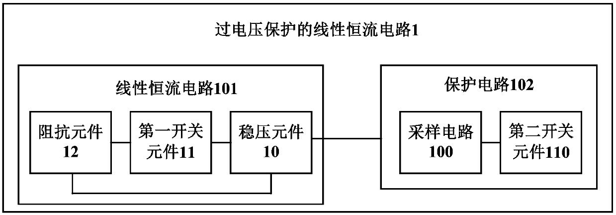
[0036] In order to solve the above technical problems, an embodiment of the present invention provides a linear constant current circuit for overvoltage protection. see figure 2 , the linear constant current circuit 1 for overvoltage protection includes a linear constant current circuit 101 and a protection circuit 102, wherein the linear constant current circuit 101 includes a voltage stabilizing element 10, a first switching ele...


PUM


Abstract

The present invention provides a linear constant current circuit for overvoltage protection, comprising a linear constant current circuit, including a voltage stabilizing element, a first switching element and an impedance element, and the linear constant current circuit is connected to a load to realize a constant current to the load Output; a protection circuit, used to reduce the operating current flowing through the load when the input voltage exceeds a specified voltage range, the protection circuit is connected to both ends of the voltage stabilizing element, including a sampling circuit and a second switching element , the sampling circuit is used to detect the voltage value of the input voltage, the second switching element is connected to the sampling circuit, when the sampling circuit detects that the input voltage exceeds the specified voltage range, the The second switching element starts to work, thereby reducing the working current flowing through the load. The invention can effectively ensure the constant current flowing through the load, and improve the stability and reliability of the linear constant current circuit for overvoltage protection.

Description

technical field [0001] The invention relates to the field of circuit protection, in particular to a linear constant current circuit for overvoltage protection. Background technique [0002] The triode constant current circuit is a commonly used LED constant current drive circuit, which is widely used in the drive circuit because of its simple structure and low cost. However, the existing triode constant current circuit generally has a big disadvantage. With the increase of the input voltage, the excess voltage is loaded on the triode or the parallel resistance, which is easy to cause a large loss of the triode or the parallel resistance. , and these losses are usually reflected in the form of heat, which affects the reliability and stability of the entire product, and even causes a fire, resulting in irreparable and serious consequences. [0003] figure 1 It is a triode constant current circuit commonly used in the prior art. This circuit mainly clamps the base voltage of ...

Claims


Application Information

Patent Timeline
Patent Type & Authority Patents(China)
IPC IPC(8): H05B33/08H02H9/04H05B44/00
CPCH02H9/045H05B45/50H05B45/37Y02B20/30
Inventor 高松李鹤
Owner OPPLE LIGHTING
Why Eureka
Try Eureka