Passenger compartment illumination device

A technology for indoor lighting and vehicles, which is applied in the direction of door lighting devices, lighting devices, and damage prevention measures for lighting devices, and can solve problems such as deformation of interior components

Inactive Publication Date: 2017-04-26
KASAI KOGYO CO LTD
View PDF9 Cites 1 Cited by
  • Summary
  • Abstract
  • Description
  • Claims
  • Application Information

AI Technical Summary

Problems solved by technology

Therefore, the inner parts are easily deformed by bending

Method used


Image

  • Passenger compartment illumination device
  • Passenger compartment illumination device
  • Passenger compartment illumination device

Examples


no. 1 approach

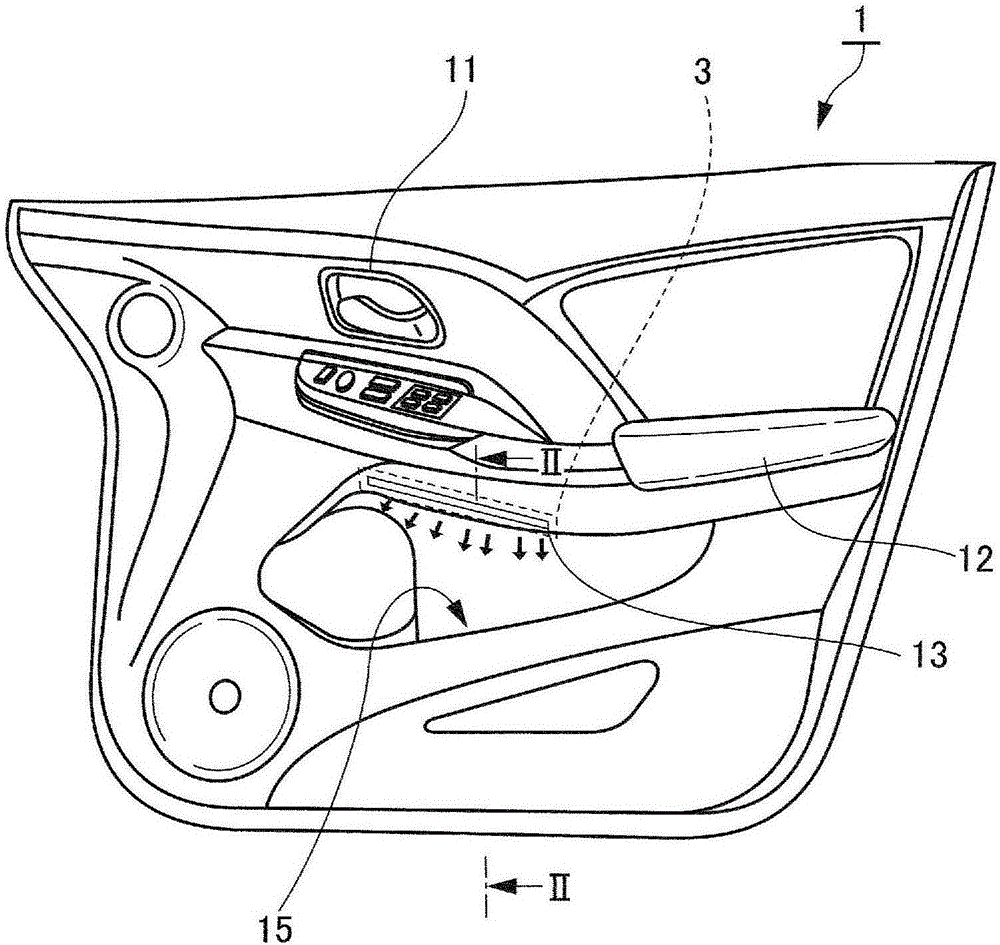
[0052] figure 1 It is a front view showing a door trim on which the vehicle interior lighting device of the present invention is mounted. figure 1 Among them, the door trim (interior parts, interior parts) 1 is relative to the body panel 2 (refer to figure 2 ) is arranged on the compartment side. The door trim 1 is equipped with an inner handle 11 operable by a driver or a passenger, and an armrest 12 extending in the traveling direction of the vehicle is provided below it. In addition, a door cover 15 is provided under the armrest 12 . The door trim 1 has, for example, an elongated opening 13 along the extending direction of the armrest 12 between the armrest 12 and the door pocket 15, and a vehicle interior lighting device (hereinafter, Referred to as lighting device) 3. In the vicinity of the door casing 15 , the light from the lighting device 3 passing through the opening 13 is irradiated.

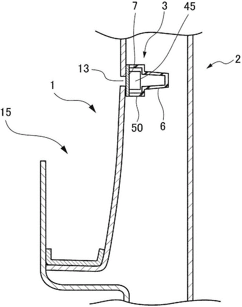
[0053] figure 2 for figure 1 Sectional view of line II-II. like figure...

no. 2 approach

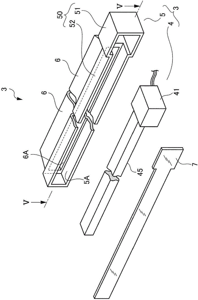
[0063] In the first embodiment, the convex portion 6 formed on the housing 50 of the lighting device 3 includes the convex portion formed on the bottom surface (side surface) of the second housing (portion for housing the duct body 45). However, it is not limited to this, such as Figure 6A As shown, the convex portion 6 may be formed on the bottom surface (side surface) of the first case (the portion housing the power supply unit 41 ). This is because the same effect can be exerted. Furthermore, it goes without saying that one can also Figure 6B Shown are formed on the bottom surfaces (side surfaces) of both the second housing 52 and the first housing 51 . Figure 6B In the case where the convex portion 6 formed on the first housing 51 is the first convex portion 61, and when the convex portion 6 formed on the second housing 52 is the second convex portion 62, the first convex portion 61 and the second convex portion The two protrusions 62 can be formed separately from ea...

no. 3 approach

[0065] In the above-described embodiment, one protrusion 6 formed on the second housing 52 of the lighting device 3 is provided along the longitudinal direction of the second housing 52 . However, if Figure 7 As shown, it can also be split into multiple settings. This is because the same effect can be exerted.


PUM


Abstract

The purpose of the present invention is to provide a passenger compartment illumination device capable of significantly reducing transmission of an impact to a vehicle body panel to an interior trim member. The passenger compartment illumination device (3) installed on the vehicle panel (2) side of an interior trim part (1) is equipped with: a light source (43); a light guide body (45) which receives incident light from the light source (43) and which extends along the interior trim part (1); and a case (50) which is installed on the interior trim part (1) with the light source (43) and the light guide body (45) being housed therein. The case (50) has, on a side surface thereof located on the vehicle panel (2) side, a projecting part (6) which projects toward the vehicle panel (2) side.

Description

technical field [0001] The present invention relates to a vehicle interior lighting device, and relates to a vehicle interior lighting device mounted on a vehicle body panel side of an interior component. Background technique [0002] Conventionally, as such a vehicle interior lighting device, as described in Patent Document 1 below, for example, a device capable of illuminating the vicinity of an armrest of a door trim (interior component) through an opening of a door trim is known. [0003] The vehicle interior lighting device is composed of the following components: a light emitting element (light source), a light guide body that makes the light of the light emitting element enter and extend along the interior part, and a case that accommodates the light emitting element and light guide body and is attached to the interior part. body. [0004] In this case, the vehicle interior lighting device mounted on the back of the interior component is narrowly formed with a relati...

Claims


Application Information

Patent Timeline
Patent Type & Authority Applications(China)
IPC IPC(8): B60Q3/217F21V8/00F21V15/01B60R13/02
CPCB60R13/02B60R13/0243B60Q3/64B60Q3/217B60Q3/54B60Q3/20B60Q3/62B60Q1/0005G02B6/0013
Inventor 漥和也
Owner KASAI KOGYO CO LTD
Why Eureka
Try Eureka