Maintenance isolation latching system and method

A technology for isolating equipment and maintenance tasks, applied to instruments, time registers, single input port/output port registers, etc., can solve the problems of many unlocking keys, difficult management and control, and inconvenient maintenance operations

Active Publication Date: 2017-05-03
ZHUHAI UNITECH POWER TECH CO LTD
View PDF5 Cites 9 Cited by
  • Summary
  • Abstract
  • Description
  • Claims
  • Application Information

AI Technical Summary

Problems solved by technology

[0005] The above two ways to realize maintenance isolation and locking involve many unloc

Method used


Image

  • Maintenance isolation latching system and method
  • Maintenance isolation latching system and method
  • Maintenance isolation latching system and method

Examples


Embodiment Construction

[0051] In order to make the purpose, technical solution and advantages of the present invention clearer, the specific implementation of the maintenance isolation and locking system and method of the present invention will be described below with reference to the accompanying drawings. It should be understood that the specific embodiments described here are only used to explain the present invention, not to limit the present invention.

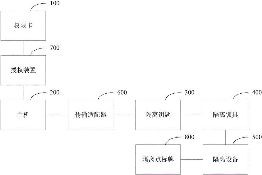
[0052] see figure 1 , in an implementation example, the inspection and isolation locking system includes an authority card 100 , a host computer 200 , an isolation key 300 and an isolation lock 400 . Wherein, the authority card 100 is used to set the maintenance operation authority of the user. The host 200 is configured to receive a maintenance task input or selected by a user, and generate a corresponding locking operation instruction according to the maintenance task input or selected by the user. The blocking operation instruction represent...


PUM


Abstract

The invention discloses a maintenance isolation latching system. The system comprises authority cards for setting maintenance authority, a host computer for receiving a maintenance task and generating a latching operation instruction according to the maintenance task, an isolation key for receiving the latching operation instruction and unlocking a corresponding isolation lock according to the latching operation instruction, and isolation locks for verifying whether the latching operation instruction received by the isolation key matches with preset unlocking information and executing unlocking if the instruction matches with the preset unlocking information, and the host computer is further used for producing an unlocking instruction after the isolated device is maintained, producing an unlocking instruction and transmitting the unlocking instruction to the isolation key to unlock the isolation lock when it is verified that maintenance permissions of all the authority cards are valid. The system can facilitate the equipment isolation operation. The invention also provides a maintenance isolation latching method.

Description

technical field [0001] The invention relates to the technical field of electric equipment maintenance, in particular to a maintenance isolation locking system and method. Background technique [0002] When overhauling equipment in industrial and mining enterprises, it is necessary to cut off all sources of energy (such as points, water, oil, gas and steam, etc.) to the overhaul equipment area to ensure the safety of overhaul equipment and maintenance personnel. Since the start / stop operation and the maintenance of the equipment are completed by different professionals, and the maintenance of equipment in the same range and in the same area will also involve different professional maintenance teams. Improper coordination or negligent management during the work may cause the wrong transmission of energy to the maintenance area and maintenance equipment, causing injury to maintenance personnel or maintenance equipment. Therefore, when the equipment is overhauled, the key hazar...

Claims


Application Information

Patent Timeline
IPC IPC(8): G07C9/00
Inventor 曾厉田世锋胡斌褚兆勇彭伟陈仲意刘拥民刘海艳
Owner ZHUHAI UNITECH POWER TECH CO LTD
Why Eureka
Try Eureka