Structure of rear lamp of motorcycle

A motorcycle and structural technology, applied in bicycle accessories, lighting and heating equipment, portable lighting devices, etc., can solve the problems of lack of rear lights, deterioration of the commercial appearance of rear lights 3 and car body, failure to comply with vehicle driving safety regulations, etc.

Inactive Publication Date: 2012-01-11
KYMCO
View PDF4 Cites 1 Cited by
  • Summary
  • Abstract
  • Description
  • Claims
  • Application Information

AI Technical Summary

Problems solved by technology

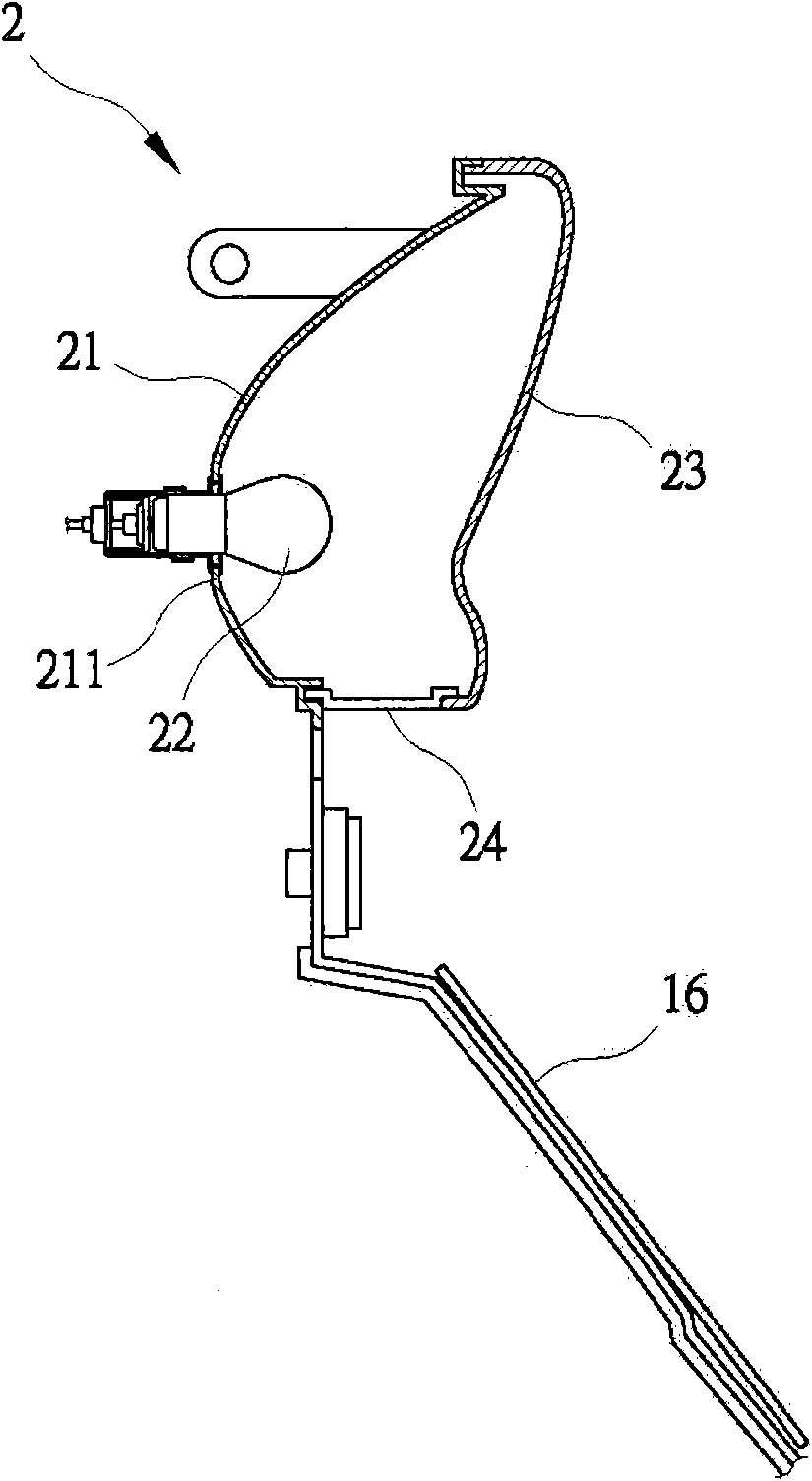
[0003] like figure 2 Shown, is the structure of an existing rear lamp 2, which is mainly composed of a base 21, a light source unit 22 and a lampshade 23, and a lamp holder 211 is provided on the base 21, and the lamp holder 211 can be used for When the light source unit 22 is fixed, the lampshade 23 is placed on the base 21 to cover the light source unit 22, and a horizontal transparent lamp housing 24 (white light) is arranged on the lower side of the lampshade 23, thereby, After the light source unit 22 is actuated (lighted), most of the light source is emitted from the lampshade 23 (red lampshade) to the rear of the car body, thereby achieving a warning effect, and part of the light source is emitted from the transparent lamp housing 24. The place illuminates the license plate 16 downwards, and then reaches the purpose of rear lamp 2 warning and lighting license plate 16; The structure of existing rear lamp 2, because the factor of mold demoulding when lampshade 23 manufactures, can cause original only to illuminate license plate 16 white light The peripheral light scattered to the rear of the vehicle body, that is, the white light used for illuminating the license plate 16 can be seen behind the vehicle body. This situation obviously cannot meet the requirements of the vehicle driving safety regulations.
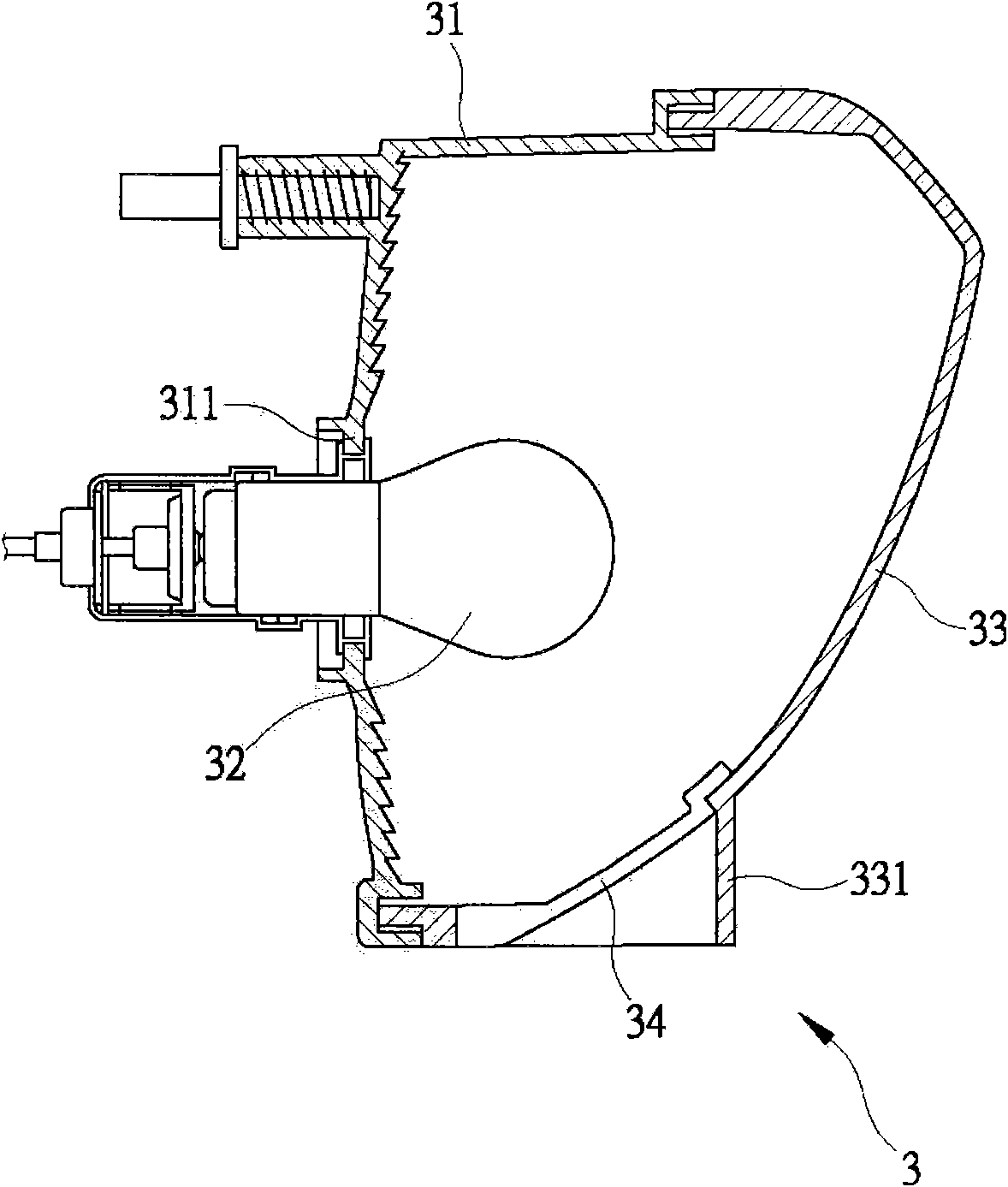
[0004] another example image 3 As shown, there is another rear lamp 3. The rear lamp 3 is mainly composed of a base 31, a light source unit 32 and a lampshade 33. A lamp holder 311 is protruded from the rear of the base 31. The lamp The seat 311 can accommodate the light source unit 32, and the lampshade 33 is covered on the base 31 so as to cover the light bulb light source unit 32; in addition, a horizontal transparent lamp housing 34 (white) is provided on the lower side of the lampshade 33 In this way, when the light source unit 32 is actuated (lighted), most of the light sources are emitted from the lampshade 33 (red lampshade) to the rear of the vehicle body, thereby achieving a warning effect, and part of the light sources are emitted from the lampshade 33 (red lampshade). The transparent lamp housing 34 illuminates the license plate 16 downwards, and then reaches the purpose of the rear light 3 warning and the illumination license plate 16. The existing rear light 3 leaks to the car body rear for the afterglow of the white light used for avoiding the illumination license plate 16. A shielding sheet 331 is protruded below the lampshade 33 near the transparent lamp housing 34. The shielding sheet 331 is the same red color as the lampshade 33, so as to block the afterglow of the white light used for illuminating the license plate 16, thereby avoiding the light on the vehicle body. See the afterglow of the white light that illuminating license plate 16 is used in the rear, to can meet the regulation of vehicle driving safety regulations; The commerciality of the appearance of the car body has seriously deteriorated, which in turn has made it more difficult to design the appearance of the car body
[0005] The above-mentioned two types of rear lights can certainly achieve the function of warning other drivers behind the car and the purpose of illuminating the license plate, but each of the aforementioned two existing rear lights has serious deficiencies that need to be solved.

Method used


Image

  • Structure of rear lamp of motorcycle
  • Structure of rear lamp of motorcycle
  • Structure of rear lamp of motorcycle

Examples


Embodiment Construction

[0044] In order to make it easier to understand the structure of the present invention and the effects that can be achieved, it is illustrated as follows:

[0045] See first Figure 4 As shown, the rear lamp 4 of the present invention includes a base 5, a light source unit 6, a lampshade 7 and a lamp housing 8;

[0046] A first lamp holder 51 is arranged above the base 5, and the main light source 61 of the light source unit 6 can be provided for the first lamp holder 51. An extension part 52 is extended from the bottom of the first lamp holder 51 to the rear of the vehicle body. A second lamp holder 53 is provided below the part 52, and the second lamp holder 53 is arranged on the front end of the extension part 52, and the second lamp holder 53 can be provided for the license plate lamp 62 of the light source unit 6, so as to make the light source The main light source 61 and the license plate light 62 of the unit 6 are arranged in a front-to-rear manner, that is, the licen...


PUM


Abstract

The invention relates to the structure of the rear lamp of a motorcycle, which comprises a base, a light source unit and a lamp cover, and is mainly characterized in that the base is provided with a first lamp holder, a main light source of the light source unit can be arranged through the first lamp holder, an extension part extending towards the rear part of the motorcycle body is arranged under the first lamp holder, a second lamp holder is arranged under the extension part, and is arranged at the front end of the extension part, the second lamp holder is used for arranging a number plate lamp of the light source unit, the position under the lamp cover, which corresponds to the second lamp holder of the base, is provided with a shielding part, and a lamp housing is arranged under the shielding part. Accordingly, the white light for the illumination of a number plate can not be fully seen from the rear of the motorcycle body, the vehicle safety laws and regulations can be met, and then, the whole light source of the rear lamp can be uniform.

Description

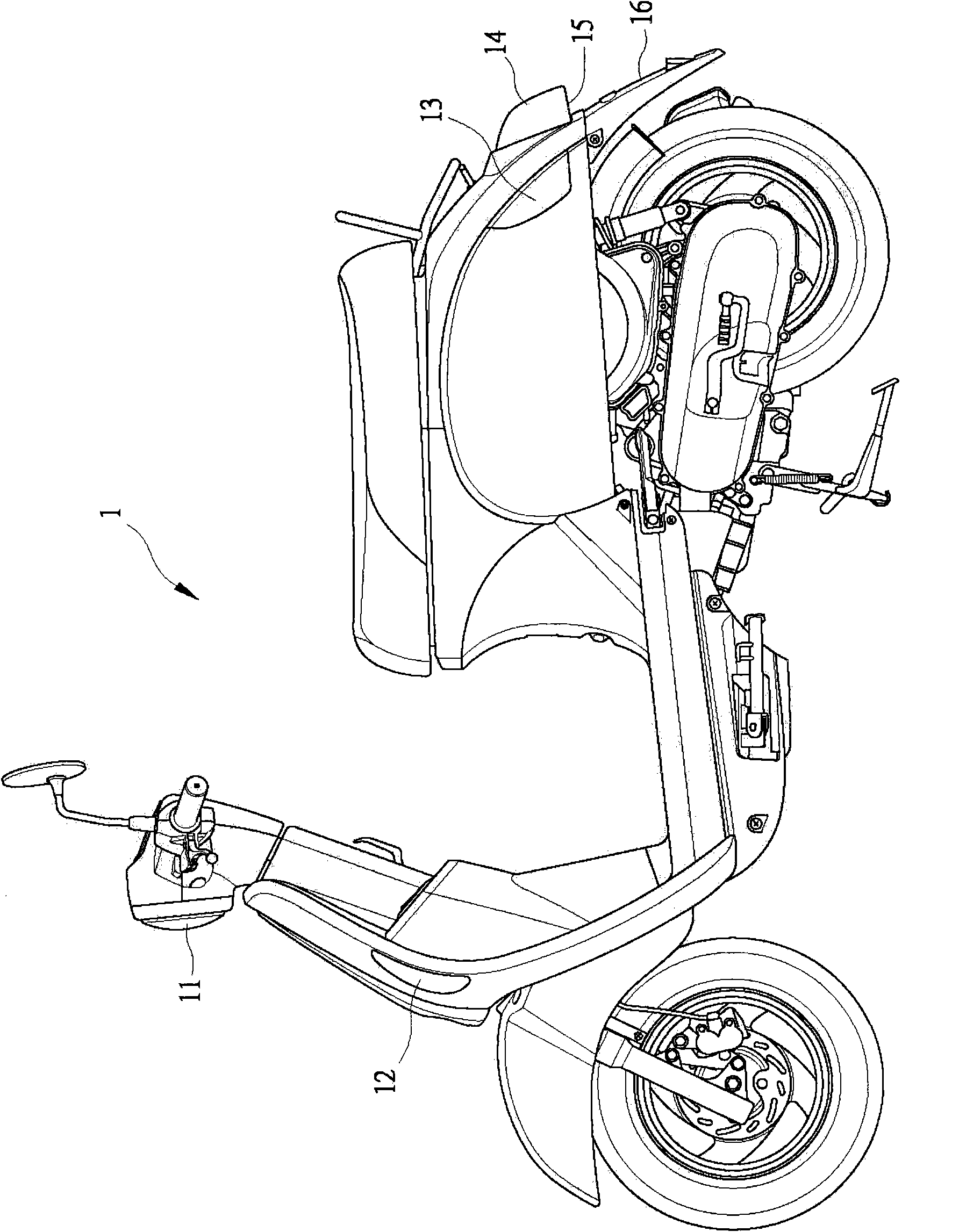
【Technical field】 [0001] The present invention relates to a rear light structure of a motorcycle, in particular to a structure that can ensure that the white light used for illuminating the license plate cannot be seen from the rear of the vehicle body. The motorcycle rear light structure with uniform light source. 【Background technique】 [0002] Motorcycle 1 is for safety and compliance with traffic regulations, such as figure 1 As shown, lamps such as headlights 11, front direction lights 12, rear direction lights 13, rear lights 14, and license plate lights 15 will be provided on the motorcycle 1, wherein the rear lights 14 are mainly used to remind other drivers behind the car. People use, so it must be a red light, and the license plate lamp 15 it is to use for illuminating the license plate 16, so its used light color is white. [0003] Such as figure 2 Shown, is the structure of an existing rear lamp 2, which is mainly composed of a base 21, a light source unit 22...

Claims


Application Information

Patent Timeline
Patent Type & Authority Applications(China)
IPC IPC(8): B62J6/04F21V1/00
Inventor 游见智
Owner KYMCO
Why Eureka
Try Eureka