
High-voltage constant-current exploder for industrial electronic detonator series network

An electronic detonator and high-voltage constant-current technology are applied to high-voltage constant-current detonators and the detonation of industrial electronic detonators. It can solve the problems of rising cost, password detonation can not meet the requirements of detonation security, etc., and achieve the effect of improving security, facilitating use and management, and improving use security.

Active Publication Date: 2012-02-01
太原新欣微电科技有限公司 +1
View PDF5 Cites 1 Cited by
  • Summary
  • Abstract
  • Description
  • Claims
  • Application Information

AI Technical Summary

Problems solved by technology

However, with the continuous development of electronic technology, simple password detonation can no longer meet people's requirements for detonation safety, especially for the management and control of detonators, and how to eliminate the hidden danger of illegal use of detonators obtained from illegal channels
Moreover, due to the increasing demand for the detonating ability of the detonator, the deficiencies of the existing detonating methods are increasingly exposed, especially for the series network, the impact of the voltage loss caused by the connection resistance on the detonation cannot be ignored. The use of low-resistance wires increases the cost

Method used


Image

  • High-voltage constant-current exploder for industrial electronic detonator series network
  • High-voltage constant-current exploder for industrial electronic detonator series network
  • High-voltage constant-current exploder for industrial electronic detonator series network

Examples


Embodiment Construction

[0031] In order to better explain the present invention and facilitate understanding, the present invention will be described in detail below through specific embodiments in conjunction with the accompanying drawings.

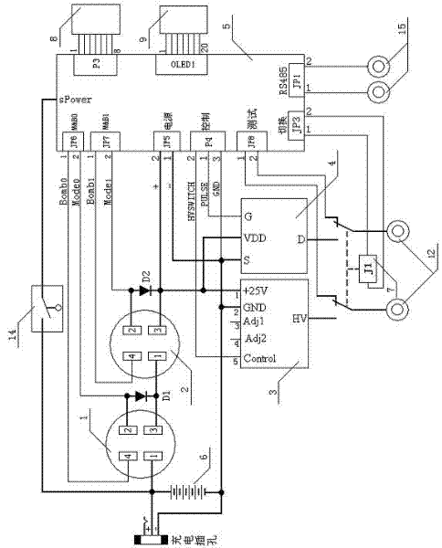
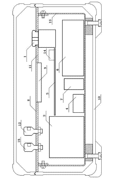
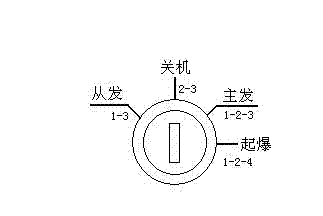
[0032] see Figure 1 to Figure 3 , The present invention relates to a high-voltage constant-current detonator used in a series network of industrial electronic detonators, comprising a high-voltage constant-current power supply 3 , a high-voltage electronic switch 4 and a CPU circuit 5 .

[0033] The high-voltage constant-current power supply can convert the output from the low-voltage DC power supply into a high-voltage and constant charging current to output to the series network of industrial electronic detonators, and form a high-voltage constant-current output loop with the series network of industrial electronic detonators, and its input can be The output end of the low-voltage DC power supply is connected, and the output end is connected to the series ne...


PUM


Abstract

The invention relates to a high-voltage constant-current exploder for an industrial electronic detonator series network, comprising a high-voltage constant-current power supply arranged in an inner container and used for providing high-voltage constant-current output, a high-voltage electronic switch for controlling the high-voltage constant-current output, a CPU (Central Processing Unit) circuit for controlling the operation of the exploder, a low-voltage direct-current power supply for providing exploder input, an ignition switch for controlling the opening / closing of the exploder, an allowable region limiting circuit for limiting an operation region of the exploder and a self-destruction circuit for burning key electrical appliance elements and damaging all control programs when the inner container of the exploder is illegally opened, wherein the ignition switch comprises two or more key switches which are sequentially connected in series and mutually independently controlled. By using the high-voltage constant-current exploder provided by the invention, management control for the exploder and explosion operation can be realized through a plurality of technical means such as double-key control, double-cipher operation, allowable region limiting and illegal opening self-destruction, the exploder can be kept in a controlled state all the time, the safety and the reliability of the explosion operation can be improved.

Description

technical field [0001] The invention relates to a detonator used for engineering blasting, especially a high-voltage constant-current detonator with high detonation safety performance, which is mainly used for detonating industrial electronic detonators connected in series. Background technique [0002] For industrial electronic detonators, in order to improve the safety of its production, use and other links, usually, each industrial electronic detonator is equipped with a detonation code, and is detonated with a special detonator. However, with the continuous development of electronic technology, simple password detonation can no longer meet people's requirements for detonation safety, especially for the management and control of detonators, and how to eliminate the hidden danger of illegal use of detonators obtained from illegal channels. Moreover, due to the increasing demand for the detonating ability of the detonator, the deficiencies of the existing detonating methods...

Claims


Application Information

Patent Timeline
IPC IPC(8): F42D1/05
Inventor 樊文欣曹文俊张柏林郝立新朱万宁张英豪张晓卫李进军
Owner 太原新欣微电科技有限公司
Learn More