Fish trap

A fish cage and fish technology, applied in fishing, fish farming, animal husbandry, etc., can solve problems such as odor, corruption, and loss of commerciality of fish, so as to reduce labor, improve labor efficiency, and improve fishing efficiency. volume effect

Inactive Publication Date: 2017-05-10
朴春宣
View PDF8 Cites 0 Cited by
  • Summary
  • Abstract
  • Description
  • Claims
  • Application Information

AI Technical Summary

Problems solved by technology

If rubbish or waste plastics etc. flow into the inside of the fish cage 10', the interior of the storage part 14 will be corrupted to generate a bad smell, etc., making it difficult to catch fish 5 by means of bait, because the caught fish 5 will be destroyed by foreign matter such as rubbish. death, so there is also concern that fish 5 will lose their commerciality

Method used


Image

  • Fish trap
  • Fish trap
  • Fish trap

Examples


Embodiment Construction

[0101] Below, the present invention and attached Figure 1 to explain.

[0102] Hereinafter, embodiments of the present invention will be described in detail with reference to the drawings. In this process, the size, shape, etc. of the constituent elements may be expressed exaggeratedly for clarity of description and convenience of description. In addition, the terms specifically defined in consideration of the structure and operation of the present invention may vary according to the user's or applicator's intention or practice. The definition of such terms should be interpreted in accordance with the meaning and concept of the technical means of the present invention on the basis of the entire content of this specification.

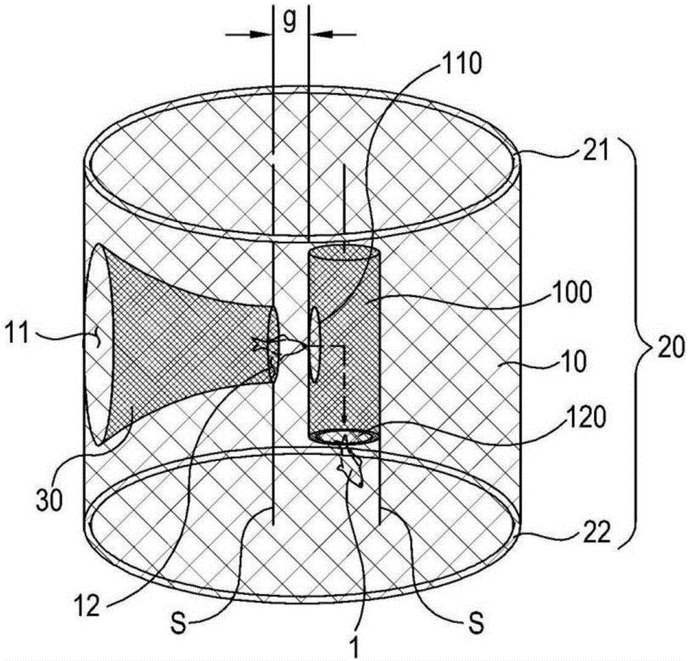
[0103] image 3 It is a figure which shows an example of the cylindrical fish cage of one Example.

[0104] As shown in the figure, the fish cage may include a fish cage net 10 , a frame 20 , a lure part 30 and an escape prevention part 100 .

[0105...


PUM


Abstract

A fish trap of the present invention comprises: a fish trap net having at least one inlet; at least one frame for supporting the fish trap net; at least one lure part having a lure hole, and formed to extend toward the inside of the frame from the inlet of the fish trap net; and an escape preventing part having isolated spaces, and provided with at least one fish passing hole through which fish, having passed through the lure hole of the at least one lure part, pass.

Description

technical field [0001] The invention relates to a fish cage. Background technique [0002] Generally, fishing rods, nets, fish cages, etc. are used as a method of catching fish living in seas or rivers. Among them, the fish cage has a larger catch than a fishing rod for catching individual fish, and the fish cage is simpler to use than a fishing net. [0003] The fish cage as described above has various forms and structures, and is also disclosed in Korean Published Utility Model Application No. 1993-0017507 and Korean Published Utility Model Application No. 1999-0000001. [0004] figure 1 To show an example of a spring fish cage in such an existing fish cage, figure 2 It is a diagram showing a method of recovering fish caught by a fish cage. [0005] As shown in the figure, fish cage 10' is formed with: frame 12, is made of cylindrical disc spring; fish cage net 11, surrounds the outer periphery of described frame 12; Entrances 12a, 12b; lures 13, the entrances 12a, 1...

Claims


Application Information

Patent Timeline
IPC IPC(8): A01K69/00
CPCA01K69/06A01K69/10A01K69/00A01K74/00A01K61/95
Inventor 朴春宣
Owner 朴春宣
Why Eureka
Try Eureka