Heating device comprising a lamp removably mounted on an associated reflector

A technology of heating devices and reflectors, applied in the direction of ohmic resistance heating devices, etc., to achieve the effect of avoiding waste

Active Publication Date: 2017-05-10
SIDEL PARTICIPATIONS SAS
View PDF4 Cites 2 Cited by
  • Summary
  • Abstract
  • Description
  • Claims
  • Application Information

AI Technical Summary

Problems solved by technology

Therefore, in the event of a lamp failure, the entire heatin

Method used


Image

  • Heating device comprising a lamp removably mounted on an associated reflector
  • Heating device comprising a lamp removably mounted on an associated reflector
  • Heating device comprising a lamp removably mounted on an associated reflector

Examples


Example Embodiment

[0036] Hereinafter, components with the same structure or similar functions will be marked with the same reference numerals.

[0037] Hereinafter, the longitudinal, vertical and lateral directions indicated by the coordinate system "L, V, T" of the drawings will be used without limitation. Here, the lateral direction is oriented from back to front.

[0038] Hereinafter, the term "inner" will be used to define a surface facing longitudinally toward the lamp tube 18, and the term "outer" will be used to define a surface facing in the opposite direction.

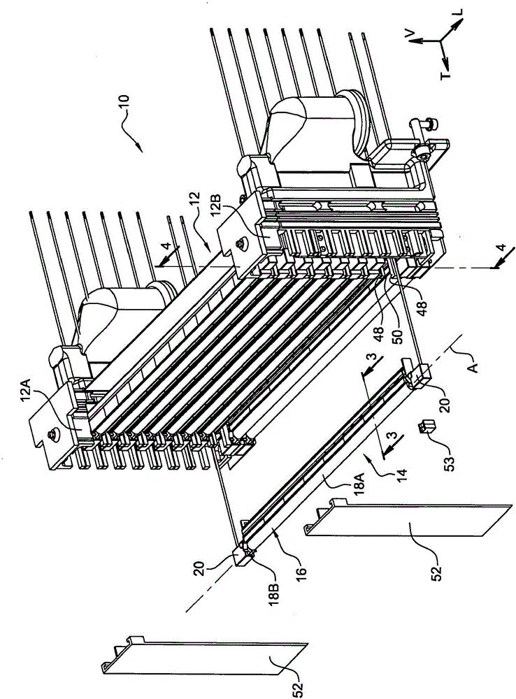
[0039] figure 1 A heating module 10 is shown therein, which is used to equip a preform heating station (not shown). The heating module 10 has a bracket 12 for supporting a plurality of identical heating devices 14.

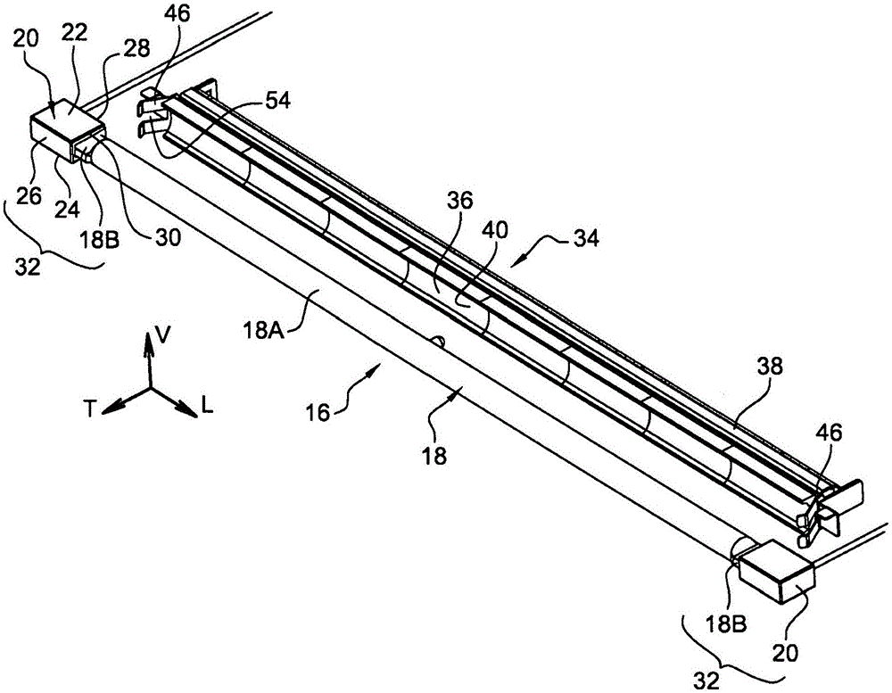
[0040] Such as figure 2 As shown, each heating device 14 has a lamp 16. The lamp 16 has a lamp tube 18 with a longitudinal axis A. The lamp tube 18 has a central hollow tube section 18A, which is hermetically closed by...


PUM


Abstract

The invention concerns a heating device (14) comprising; a tubular lamp (16) comprising two free end sections (32); at least one reflector (34) that extends longitudinally at a predefined transverse distance (D) from the lamp (16); two holding members (46) for holding the lamp (16) in a transverse position relative to the reflector (34), each holding member (46) being attached to the reflector (34); characterised in that each free end section (32) of the lamp (16) is removably mounted on each holding member (46) by reversibly interlocking a portion of the free end section (32) of the lamp with a housing (54) of complementary shape in a direction orthogonal to the longitudinal direction.

Description

technical field [0001] The invention relates to a heating device, in particular for heating preforms made of thermoplastic material, the heating device having a lamp and a reflector fitted with the lamp. [0002] The invention more particularly relates to a heating device, in particular for heating preforms made of thermoplastic material, the heating device having: [0003] - lamps having a tube having two free end sections, each of which has an end clip of the tube and an end socket fixed to the end clip; [0004] - at least one reflector extending longitudinally at a defined transverse distance from the lamp; [0005] - two holders for holding the lamp in a transverse position relative to the reflector, each holder being fixed to the reflector. Background technique [0006] It is known to manufacture containers of thermoplastic material by shaping preforms, for example by blowing or stretch blowing. In order to carry out the forming operation, the body of the preform mu...

Claims


Application Information

Patent Timeline
IPC IPC(8): B29C49/68B29C49/06B29C49/64
CPCB29C49/68B29C49/06B29C49/6418B29C2049/023B29C2949/0715B29C49/6835B29C49/6427B29K2101/12H05B3/0057
Inventor P·厄兹布洛克J-F·莫里斯
Owner SIDEL PARTICIPATIONS SAS
Why Eureka
Try Eureka