Folded Optical Array Camera Using Refracting Prisms

A prism array and camera technology, applied in optics, prisms, cameras, etc.

Active Publication Date: 2019-08-23
QUALCOMM INC
View PDF10 Cites 0 Cited by
  • Summary
  • Abstract
  • Description
  • Claims
  • Application Information

AI Technical Summary

Problems solved by technology

The longer focal length makes it possible to implement features such as optical zoom, and it is possible to incorporate more complex optics (which require more space than is typically provided by traditional mobile cameras), such as adding more optical elements

Method used


Image

  • Folded Optical Array Camera Using Refracting Prisms
  • Folded Optical Array Camera Using Refracting Prisms
  • Folded Optical Array Camera Using Refracting Prisms

Examples


Embodiment Construction

[0021] I. introduction

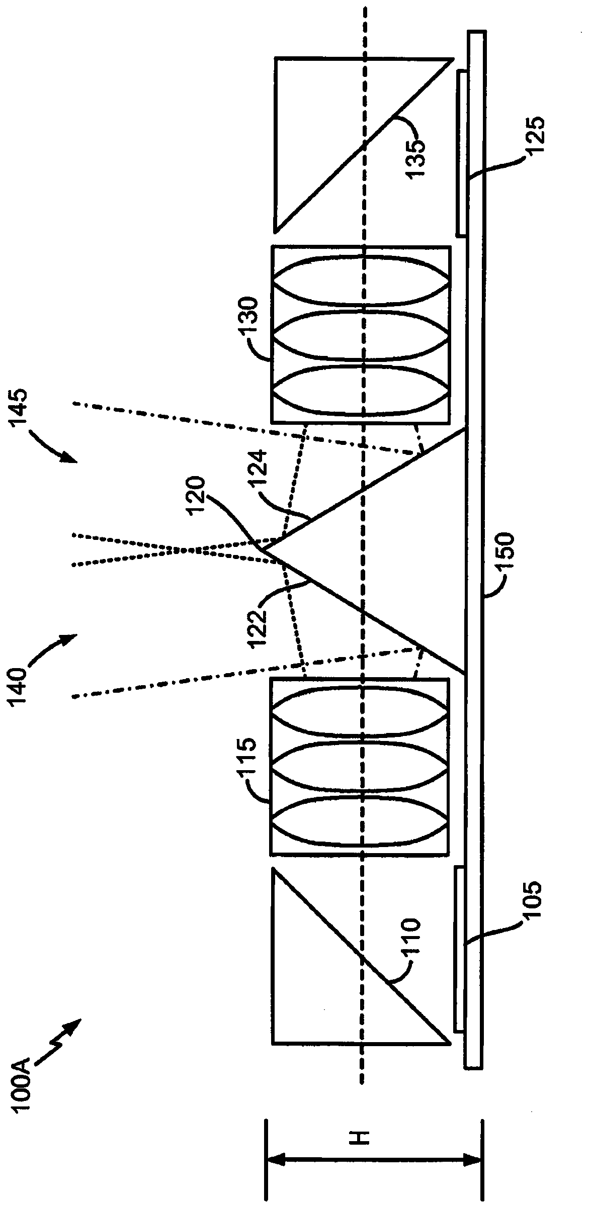
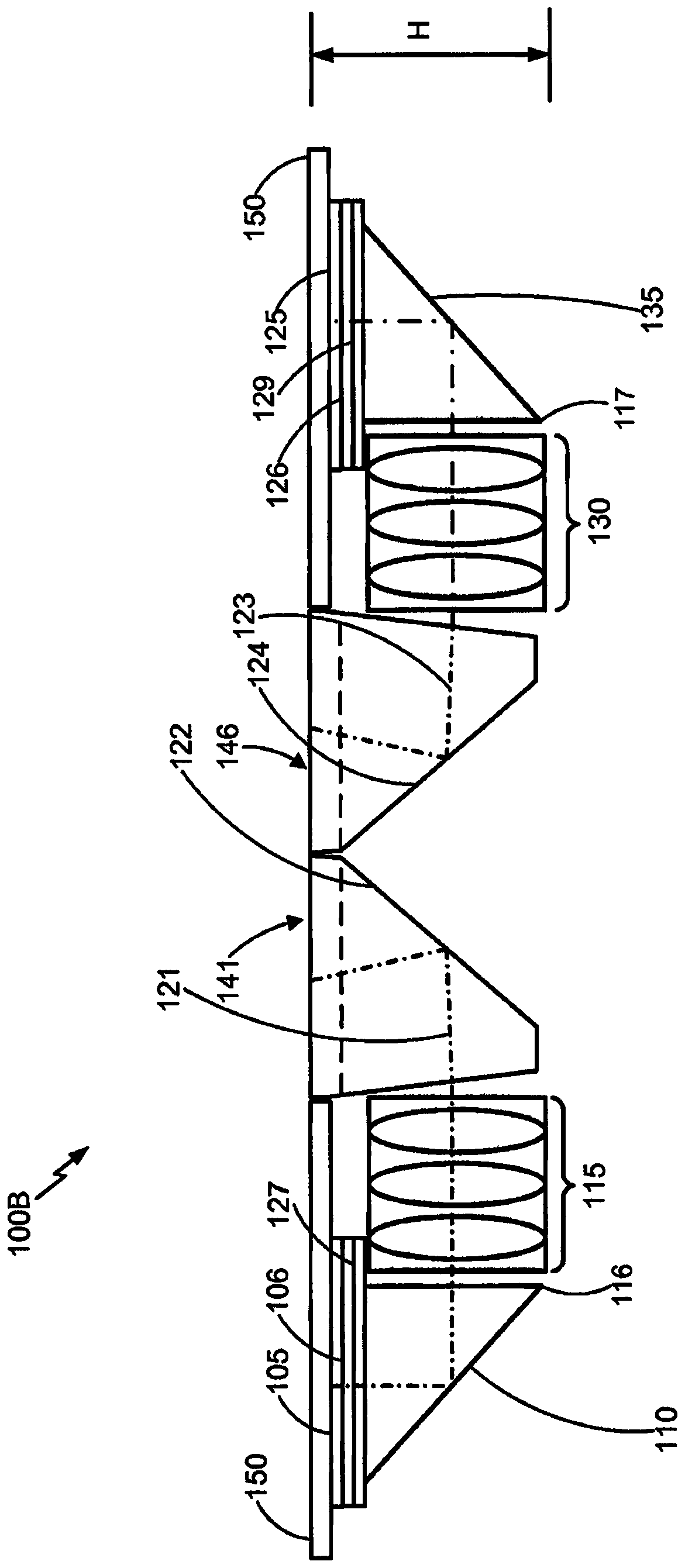
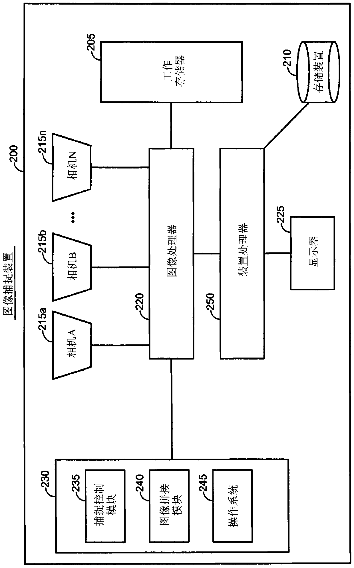
[0022] Embodiments disclosed herein provide systems, methods, and apparatus for using array cameras with folded optics to produce images with a wide field of view that are substantially free of parallax and tilt artifacts. Aspects of the invention relate to array cameras with a wide field of view (eg, approximately 180 degrees). Replacing mirrors with prisms solves both problems mentioned above at the same time - the camera sees beyond the central mirror, and the limited FOV of each camera. For example, a wide range of prism design cameras do not see above the edges or vertices of the prisms due to the effect of total internal reflection. This solves the first problem very effectively. Also, the camera gets a wider FOV. In one category of design, this has to do with the introduction of chromatic aberration. Another embodiment of the prism array camera design is completely free of aberrations. With higher index glass and other materials, the fiel...


PUM

PropertyMeasurementUnit
refractive indexaaaaaaaaaa

Abstract

Aspects relate to a prism array camera with a wide field of view. For example, the prism array camera may use, for example, a central refractive prism having multiple surfaces or facets to split incident light containing an image of an object into multiple portions for capture by sensors in the array. The prisms can have a refractive index of about 1.5 or higher, and can be shaped and positioned to reduce chromatic aberration artifacts and increase the FOV of the sensor. In some examples, a negative lens can be incorporated into or attached to the camera-facing surface of the prism to further increase the FOV.

Description

technical field [0001] The present invention relates to imaging systems and methods including multi-camera arrays. More particularly, the present invention relates to systems and methods for enabling low profile imaging systems and mobile devices while maintaining or improving image quality. Background technique [0002] Many mobile devices, such as mobile telephones and tablet computing devices, include cameras that can be operated by a user to capture still and / or video images. Because mobile devices are typically designed to be relatively small, it may be critical to design the camera or imaging system as thin as possible in order to remain a low profile mobile device. Folded optical image sensor arrays ("array cameras") allow the creation of low-profile image capture devices without shortening the focal length or reducing the resolution of images within the sensor array's field of view. By using primary and secondary surfaces to redirect light toward each sensor in the...

Claims


Application Information

Patent Timeline
Patent Type & Authority Patents(China)
IPC IPC(8): G03B17/17H04N5/225H04N5/232H04N5/341
CPCG03B17/17G03B37/04H04N23/45H04N23/55H04N23/698H04N25/41G02B13/0065G06T3/4038G02B13/007G02B13/06G02B5/045Y10T29/49119Y10T29/49828G02B13/006G02B5/04G03B30/00
Inventor T·G·格奥尔基耶夫
Owner QUALCOMM INC
Why Eureka
Try Eureka