Bionic four-foot robot hind limb with tensegrity structure

A tensegrity structure, quadruped robot technology, applied in the direction of motor vehicles, transportation and packaging, etc., can solve the problems of robot motion failure, leg joint failure, etc., to improve stability and service life, improve motion energy efficiency, eliminate Effects of wear and impact

Active Publication Date: 2017-05-17
JILIN UNIV
View PDF13 Cites 8 Cited by
  • Summary
  • Abstract
  • Description
  • Claims
  • Application Information

AI Technical Summary

Problems solved by technology

[0006] The purpose of the present invention is to solve the problem that the lower limbs used by the existing quadruped robots fail the leg members and leg joints under the action of various types of loads, Problems leading to robot locomotion failure, while providing a biomimetic quadruped robot hindlimb with tensegrity structure

Method used


Image

  • Bionic four-foot robot hind limb with tensegrity structure
  • Bionic four-foot robot hind limb with tensegrity structure
  • Bionic four-foot robot hind limb with tensegrity structure

Examples


Embodiment Construction

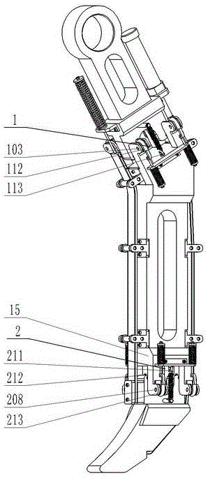
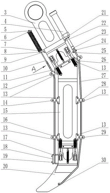
[0022] see figure 1 , figure 2 , image 3 and Figure 4 As shown, this embodiment includes a knee joint 1 , an ankle joint 2 , a first leg member 3 , a second leg member 15 , and a third leg member 20 .

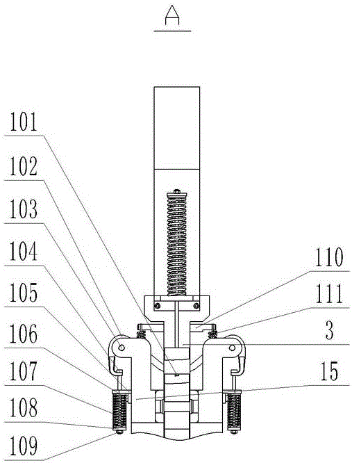
[0023]The knee joint 1 is composed of a first set screw 101, a first drag cable 102, a first pin 103, a first pull rod 104, a first spring support 105, a first screw 106, a first compression spring 107, a first pad Sheet 108, first nut 109, first spring hanger 110, first extension spring 111, first pulley 112, and first eyebolt 113. Wherein, a pair of first stay cables 102 passes through the bottom of the first leg member 3, and the relative position of the first stay cable 102 and the first leg member 3 is guaranteed by a pair of first set screws 101. The pulley 112 is symmetrically arranged on the top of the second leg member 15 through the four first pins 103 , and guides and supports the first cable 102 . Both ends of the first cable 102 cross the first pulley 112 a...


PUM


Abstract

The invention discloses a bionic four-foot robot hind limb with a tensegrity structure. The hind limb comprises a knee joint, an ankle joint, a first leg component, a second leg component, a third leg component and the like. A first inhaul cable, a second inhaul cable, a first torsion spring, a second torsion spring, a third inhaul cable and a fourth inhaul cable form a tensioned part of the tensegrity structure of the robot hind limb together, and the tension part and stressed parts including the first leg component, the second leg component, the third leg component and the like complete movement of the robot hind limb together. The third inhaul cable and the fourth inhaul cable are matched with the first inhaul cable, the second inhaul cable, the first torsion spring and the second torsion spring to achieve movement of the knee joint and the ankle joint, and abrasion and impact between the first leg component and the second leg component and between the second leg component and the third leg component are avoided. Meanwhile, shearing stress concentrated distribution of the leg components of the robot hind limb in the earth contacting impact process is effectively avoided due to the third inhaul cable and the fourth inhaul cable, and accordingly the leg components of the robot hind limb are protected against shear failure.

Description

technical field [0001] The invention relates to the technical field of mechanical bionic engineering, in particular to a bionic quadruped robot hind limb based on a tensioned integral structure applied to a quadruped robot. Background technique [0002] Because quadruped walking has the advantages of good stability and strong adaptability, research on quadruped robots has been widely carried out in the world in recent years. However, for the purpose of simplifying design and control, the joints (knee joints and ankle joints, etc.) of most quadruped robots are designed as hinged connections. Because the working environment of quadruped robots is usually very complex, the leg components and joints of the lower limbs are often subjected to various types of loads such as tension and compression, shearing, bending and torsion, especially when they are in high-speed dynamic motion mode, the existing quadruped robots Body movements often fail due to failure of leg components and j...

Claims


Application Information

Patent Timeline
Patent Type & Authority Applications(China)
IPC IPC(8): B62D57/032
CPCB62D57/032
Inventor 钱志辉周亮杨茗茗黎亦磊任雷任露泉
Owner JILIN UNIV
Why Eureka
Try Eureka