
A roof rainwater treatment system and construction method
A technology of treatment system and construction method, applied in the direction of runoff/rainwater treatment, water/sewage multi-stage treatment, biological water/sewage treatment, etc., to achieve the effect of alleviating the scarcity of water resources and improving the efficiency of resource utilization
Patent Information
- Authority / Receiving Office
- CN · China
- Patent Type
- Patents(China)
- Current Assignee / Owner
- Publication Date
- 2020-04-07
Smart Images
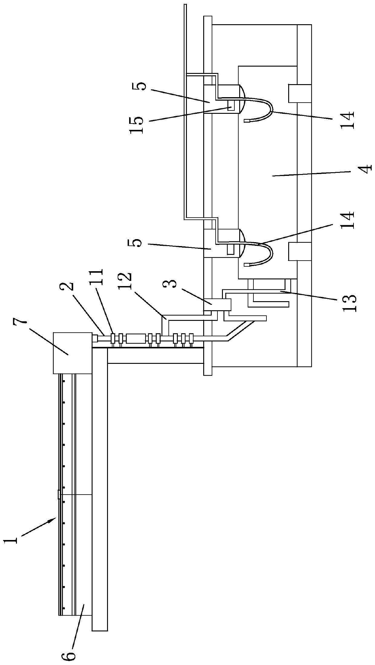
Figure 1 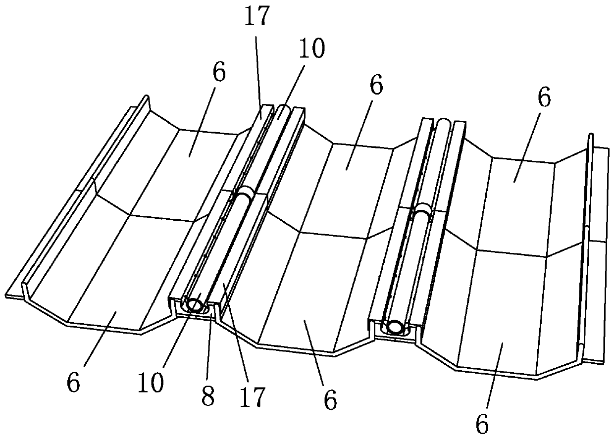
Figure 2 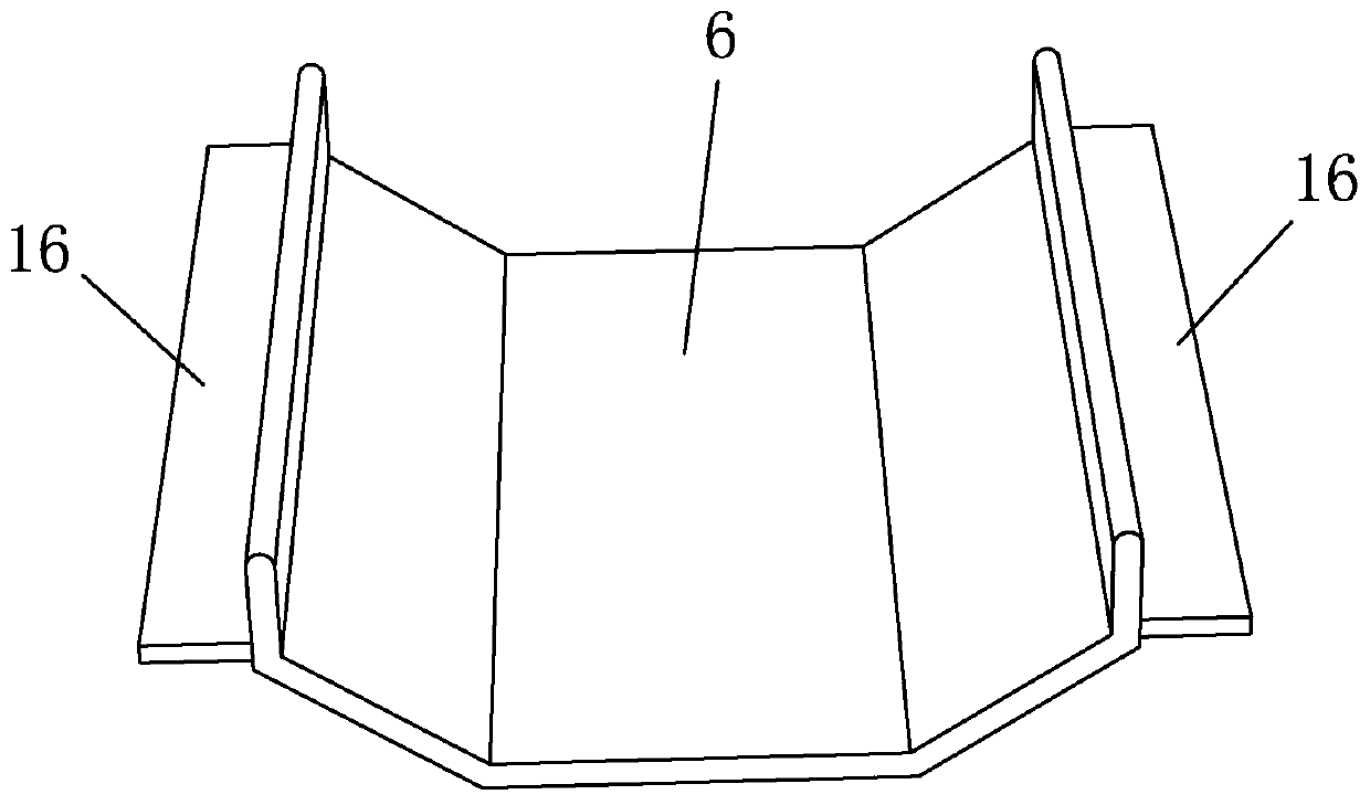
Figure 3
Abstract
Description
technical field
[0001] The invention belongs to the technical field of water resource utilization, and in particular relates to a house roof rainwater treatment system and a construction method. Background technique
[0002] With the advancement of urbanization, the increase of ground hardening has changed the original hydrological characteristics, resulting in increased rainwater runoff, frequent water accumulation on the road surface, and frequent large-scale water accumulation in some cities. The drop in groundwater level has intensified. In addition, the problem of water shortage in my country's cities is becoming more and more serious. The resource-based water shortage in the northern region and the water quality-based water shortage in the southern region. In this environment, the government proposed the goal of building a "sponge city" and supported it in various aspects such as policy and finance.
[0003] Sponge city, as the name suggests, is like a sponge. During...
Examples
Embodiment Construction
[0029] Such as Figure 1 to Figure 5 Shown is a house roof rainwater treatment system in the present invention, including a rainwater collection pipe network 1, a rainwater standpipe 2, a cyclone filter device 3, a rainwater collection tank 4 and a water intake system 5.
[0030] The rainwater collecting pipe network 1 includes a flashing plate 6 and a collecting water tank 7 , and the flashing plate 6 is connected to the collecting water tank 7 . Two adjacent flashing boards 6 on the left and right are fixedly connected, a U-shaped steel 8 is arranged between the two adjacent left and right flashing boards 6, a spacer 9 is arranged on the U-shaped steel 8, and a horizontal pipe 10 is arranged on the spacer 9, and the horizontal pipe 10 is arranged on the spacer 9. The pipe 10 is connected to the collection tank 7 . Both sides of the flashing board 6 are provided with support plates 16, and the U-shaped steel 8 is arranged on the support board 16. The support board 16 can be us...