Check patentability & draft patents in minutes with Patsnap Eureka AI!

Pod drive with traction propeller

A driving device, propeller technology, applied in the direction of rotating propeller, transportation and packaging, rotary propeller, etc., can solve the problems of resistance, stabilizer not optimizing flow, etc., to achieve the effect of reducing complexity

Active Publication Date: 2018-11-30
SIEMENS ENERGY GLOBAL GMBH & CO KG
View PDF8 Cites 0 Cited by
  • Summary
  • Abstract
  • Description
  • Claims
  • Application Information

AI Technical Summary

Problems solved by technology

However, if the vessel has drastically changing driving characteristics, the stabilizer does not flow optimally and even partially causes additional drag

Method used


Image

  • Pod drive with traction propeller
  • Pod drive with traction propeller
  • Pod drive with traction propeller

Examples


Embodiment Construction

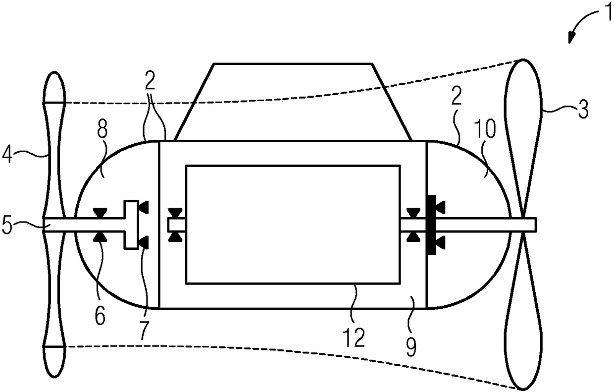
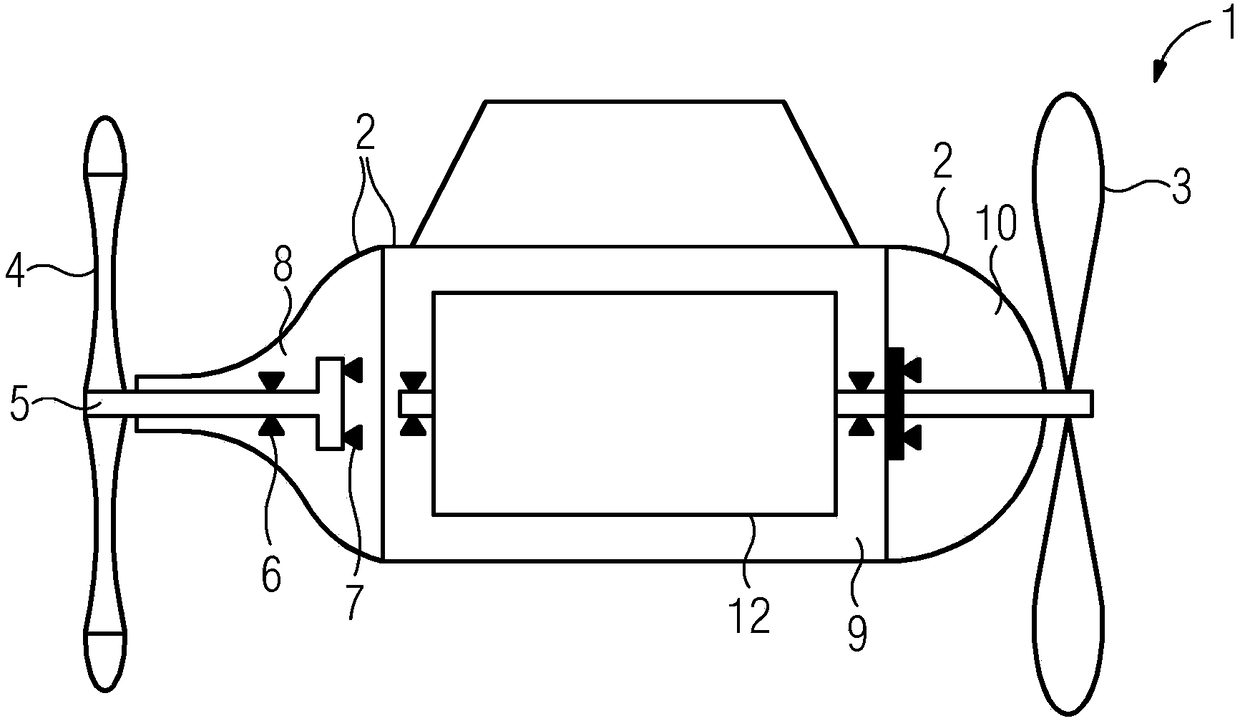
[0027] figure 1 Shown is a gondola drive 1 according to the invention with a housing 2, a traction propeller 3 and a guide wheel 4 at a guide wheel shaft 5, which is supported in part of the housing 2 by two bearings 6, 7. in paragraph 8. An electric motor 12 for driving the traction propeller 3 is accommodated in the other section 9 of the housing 2 , the shaft of which is supported by further bearings in the sections 9 and 10 . The dotted line between the traction propeller 3 and the guide wheel 4 indicates the jet constriction of the propeller jet, by means of which a guide wheel 4 with a diameter similar to that of the traction propeller 3 can be used. If the section 9 is sealed separately from the guide wheel section 8 , the guide wheel adapter 8 can function without an essential sealing element, since it is separated spatially and from the point of view of tightness from the rest of the POD. It is therefore advantageous here to use (sea) water lubricated bearings 6 , 7...


PUM


Abstract

The invention relates to a pod propulsion system (1) for a floating device, having a housing (2) and at least one tractor propeller (3), and to a floating device comprising such a pod propulsion system (1). In order to provide a pod propulsion system which is improved in relation to the known solutions, it is proposed, for example, to arrange at least one guide wheel (4) on a guide wheel shaft (5) mounted by means of at least one bearing on the side of the housing (2) opposite the at least one tractor propeller (3).

Description

technical field [0001] The invention relates to a pod drive for a floatation device, having a housing and at least one traction propeller. The invention also contemplates a floatation device with such a pod drive. Background technique [0002] Such a pod drive, also referred to as a POD drive, can in principle be used in any floating installation and is used not only as a drive but also as an "active paddle". The pod drive can be driven mechanically—for example by a diesel engine—or by an electric motor, and is connected to the floatation device via a rotatable shaft. As in all drives, the question of efficiency is also decisive in pod drives, since relatively small increases in efficiency and thus corresponding cost reductions have already been achieved with very significant fuel savings especially in large ships . In this case, the invention relates in particular to the recovery of rotational energy from the propeller jet. [0003] There are various possibilities for r...

Claims


Application Information

Patent Timeline
Patent Type & Authority Patents(China)
IPC IPC(8): B63H1/28B63H5/10
CPCB63H1/28B63H5/10B63H2005/075
Inventor 托尔本·克里夫斯
Owner SIEMENS ENERGY GLOBAL GMBH & CO KG
Features
  • R&D
  • Intellectual Property
  • Life Sciences
  • Materials
  • Tech Scout
  • Unparalleled Data Quality
  • Higher Quality Content
  • 60% Fewer Hallucinations
Learn More