Executing mechanism of static pointing type rotary steerable drilling tool

A technology for rotary steerable drilling and actuators, which is applied in directional drilling and other directions, can solve the problems such as the lack of a disclosed spherical contact surface to form a seal, the insufficient pressure bearing capacity of the flexible bellows seal, and its easy to fail too quickly, and achieve long service life, The effect of high pressure bearing capacity and flexible swing

Pending Publication Date: 2018-04-20
DEZHOU UNITED GASOLINEEUM MACHINERY
View PDF3 Cites 110 Cited by
  • Summary
  • Abstract
  • Description
  • Claims
  • Application Information

AI Technical Summary

Problems solved by technology

The flexible bellows seal maintains a seal between the sliding tool collar and the circular seal retainer, thereby preventing the intrusion of drilling fluid into the internal oil storage cavity, however, the flexible bellows seal has insufficient pressure capac...

Method used


Image

  • Executing mechanism of static pointing type rotary steerable drilling tool
  • Executing mechanism of static pointing type rotary steerable drilling tool
  • Executing mechanism of static pointing type rotary steerable drilling tool

Examples


Embodiment 1

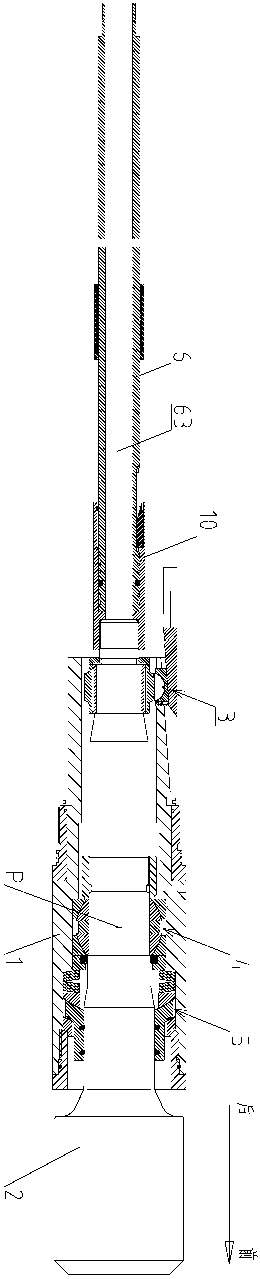
[0040] figure 1 It is a schematic structural diagram of the first preferred embodiment of the static directional rotary steering drilling tool actuator of the present invention.

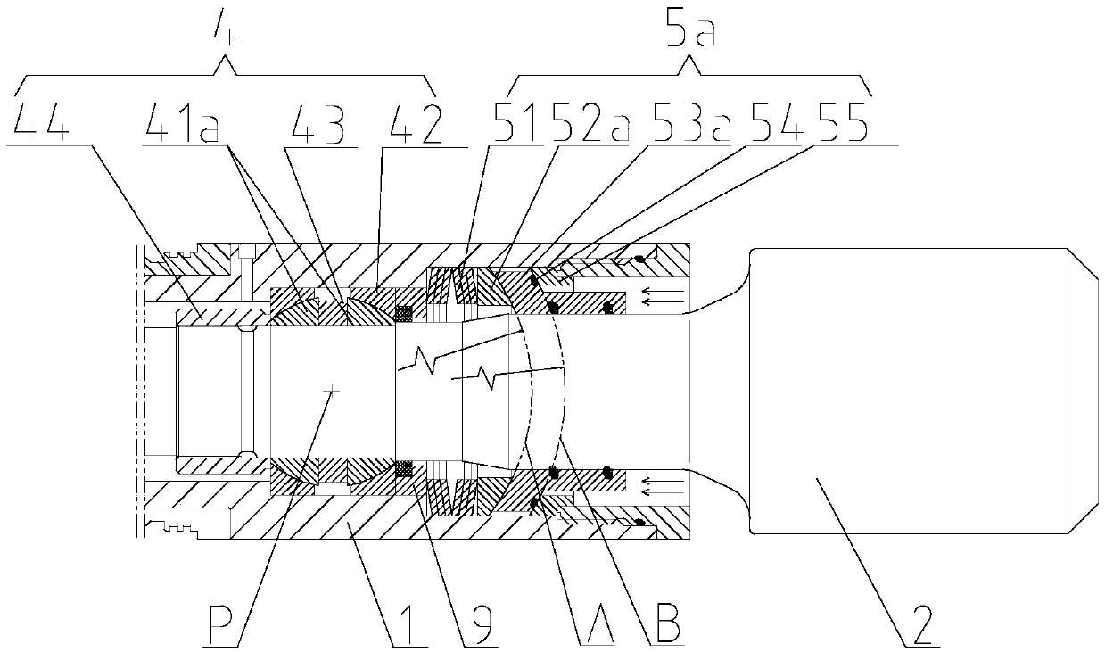
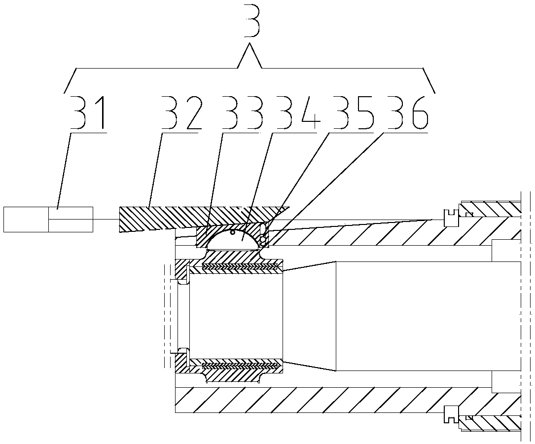
[0041] Please refer to figure 1 As shown, the actuator of the static directional rotary steering drilling tool of the present invention includes a housing 1, a transmission shaft 2, a biasing unit 3, a joint connection unit 4, a sealing unit 5 and a flexible shaft 6.

[0042] Such as figure 1 As shown, the front end of the transmission shaft 2 is connected with a drill bit, the rear end of the transmission shaft 2 is in transmission and sealing connection with the flexible shaft 6, the center of the flexible shaft 6 is provided with a guide hole 63, and the transmission shaft 2 is provided with a through hole ( figure 1 (Not shown), the drilling fluid passes through the diversion hole 63 of the flexible shaft 6 and the through hole of the transmission shaft 2 to the drill bit.

[0043] Such as figure 1 As sh...

Embodiment 2

[0063] The difference between this embodiment and embodiment 1 is only Figure 5 As shown, the inner ball sleeve 41b is integral. This technical solution reduces the number of components and improves the installation accuracy.

Embodiment 3

[0065] The difference between this embodiment and embodiment 1 lies in Image 6 As shown, the structure of the sealing unit 5b is different. The sealing unit 5b includes a fixed ball head 52b, a swing ball seat 53b, an elastic member 51 and a retaining ring 56, where the fixed ball head 52b is adjacent to the backing ring 9, and the swing ball seat 53b The spherical surface is connected with the spherical surface of the fixed ball head 52b to form a third spherical contact surface C. The third spherical contact surface C has the same central pivot point P as the inner ball sleeve 41b. A spherical seal 54 can be installed on the fixed ball head 52b. 的槽。 The slot.

[0066] Such as Image 6 As shown, the swing ball seat 53b is sealed and rotatably connected with the transmission shaft 2, for example, a sealing ring groove may be provided on the inner hole of the swing ball seat 53b. One end of the elastic member 51 of this embodiment is connected to the swing ball seat 53b, and the o...


PUM


Abstract

The invention provides an executing mechanism of a static pointing type rotary steerable drilling tool, and belongs to the technical field of rotary guide drilling tools. The executing mechanism comprises a shell (1) and a transmission shaft (2), wherein the shell (1) is connected with the transmission shaft (2) through joint connection units (4), the shell (1) is connected with the transmission shaft (2) through sealing units (5), and the sealing units (5) are used for isolating the joint connecting units (4) from drilling fluid. Each sealing unit (5) comprises at least one sealed spherical contact surface, wherein the spherical contact surface and the joint connection units (4) have the same central pivot point (P).

Description

Technical field [0001] The invention relates to the technical field of rotary steering drilling tools, in particular to a static pointing type rotary steering drilling tool actuator. Background technique [0002] With the acceleration of oilfield development and the development of oil drilling technology, there are more and more difficult directional wells, such as highly deviated wells, extended reach wells, and "S" wells. These wells have complex trajectories, high downhole friction, and conventional screw Because the body and the drilling tool cannot be rotated during directional drilling, the drilling tool can only slide drilling, resulting in unstable tool surface during directional drilling and prone to sticking accidents. [0003] The rotary steering drilling tool is currently the most advanced and efficient petroleum directional drilling tool in the world. It can realize the drilling operation and control of the three-dimensional complex well trajectory in the drilling tool...

Claims


Application Information

Patent Timeline
IPC IPC(8): E21B7/04
CPCE21B7/04
Inventor 杨成永张桂昌程贵华薛庆华张浩谦王继平魏岳
Owner DEZHOU UNITED GASOLINEEUM MACHINERY
Why Eureka
Try Eureka