Wedge unit and braking device

A braking device, wedge-shaped technology, applied in the direction of brake actuators, gear transmission mechanisms, mechanical equipment, etc., can solve problems such as limiting the service life of rollers or actuating pistons and/or wedges, hindering brakes, etc.

Inactive Publication Date: 2017-05-24
SAF HOLLAND GMBH
View PDF7 Cites 4 Cited by
  • Summary
  • Abstract
  • Description
  • Claims
  • Application Information

AI Technical Summary

Problems solved by technology

[0005] In the case of higher input forces and / or greater translations due to the reduction of the wedge angle, especially in order to obtain higher braking moments, higher surface pressures are exerted on the raceways and rollers , which may limit the service life of the rollers or actuating piston and / or wedge
It must also be pointed out that the roller presses into the running surface of the piston and can thus block the brake

Method used


Image

  • Wedge unit and braking device
  • Wedge unit and braking device

Examples


Embodiment Construction

[0028] Throughout the figures, identical or equivalent elements are marked with the same reference numerals.

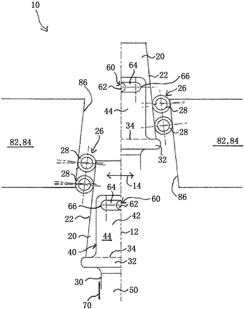
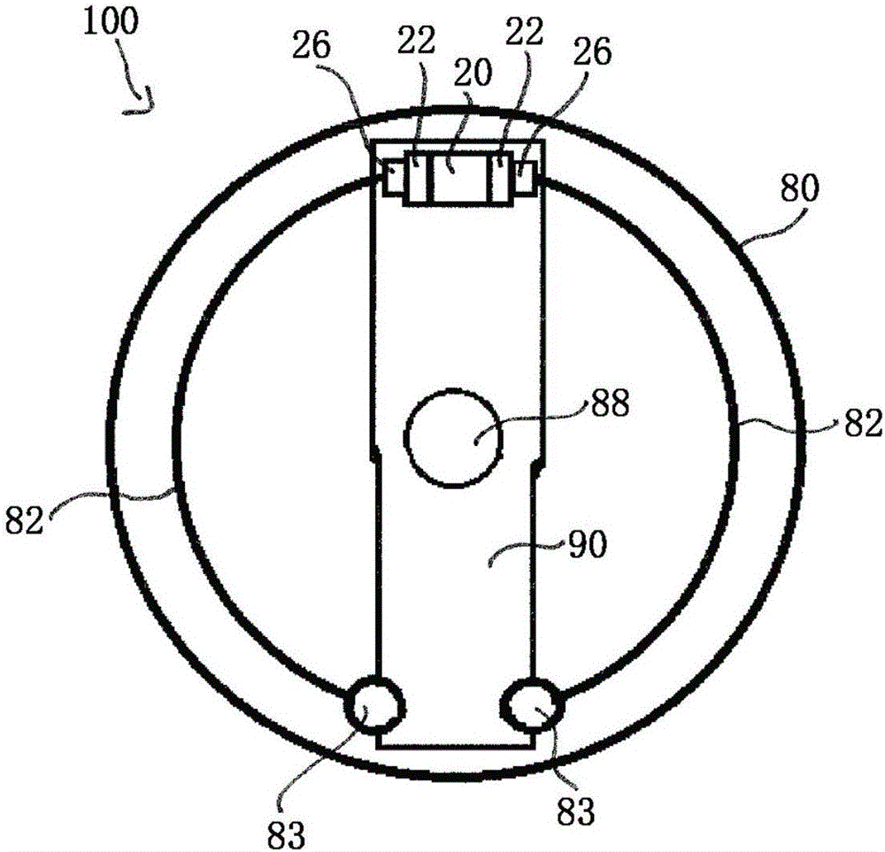
[0029] figure 1A wedge unit 10 of a braking device 100 according to the invention is shown. The wedge unit 10 comprises a wedge 20 whose center plane (symmetry plane) is oriented parallel to the actuation direction 12 (axial movement direction, lifting direction). Furthermore, the multi-part wedge unit 10 also comprises an adjustment element 30 for displacing the wedge 20 in the actuation direction 12 . The adjusting element 30 comprises a pressure plate 32 for displacing the wedge 20 substantially in the actuating direction 12 so that the braking device 100 can be moved from the unloaded position into the braking position. To this end, the pressure plate 32 comprises a pressure surface 34 extending substantially perpendicularly to the actuation direction 12 . The pressure surface 34 cooperates with a corresponding opposing pressure surface of the wedge 20 .

[00...


PUM


Abstract

The invention relates to a wedge unit for a braking device (100) with brake pad supports (82), comprising a wedge (20) which can be moved along in a direction of actuation (12), for separating the brake pad supports (82), characterised in that an actuating element (30) for moving the wedge (20) is provided and that said wedge (20) is arranged such that it can move relative to the actuating element (30).

Description

technical field [0001] The invention relates to a wedge unit for a brake device and a brake device with the wedge unit, in particular to a drum brake with the wedge unit. Background technique [0002] Wedge units for actuating brakes, in particular drum brakes, have long been known in the prior art. In wedge brakes or wedge drum brakes, the brake lining carrier, which is pivotally mounted on the brake carrier, is pushed away by the wedge to trigger the braking process. Thus, the brake linings connected to the brake lining carrier come into contact with the inner side of the rotating brake drum and brake said brake drum. At its end facing the wedge, the brake lining carrier has a so-called actuating piston, the active surface of which is pressed by the wedge unit. [0003] In known wedges with a floating mounted wedge, the wedge moves and thus assumes a tilted position, due to a force balance on the wedge face due to the floating mounted wedge, i.e. the same force on the we...

Claims


Application Information

Patent Timeline
Patent Type & Authority Applications(China)
IPC IPC(8): F16D65/18F16D65/22
CPCF16D65/18F16D2121/14F16D2125/36F16D2125/66F16D65/22F16D2125/18
Inventor 奥拉夫·德鲁斯
Owner SAF HOLLAND GMBH
Why Eureka
Try Eureka