Shoe cabinet with cleaning function

A shoe cabinet and functional technology, applied in the field of shoe cabinets, can solve the problem of not being able to clean the upper and the sole of the shoe

Inactive Publication Date: 2017-05-31
湖州黛丝娅鞋业有限公司
View PDF11 Cites 4 Cited by
  • Summary
  • Abstract
  • Description
  • Claims
  • Application Information

AI Technical Summary

Problems solved by technology

[0006] In order to overcome the disadvantage that the existing shoe cabinet cannot clean the upper and the sole of the shoe, the technical problem to be solved by the present invention is to provide a shoe cabinet with a cleaning function

Method used


Image

  • Shoe cabinet with cleaning function
  • Shoe cabinet with cleaning function
  • Shoe cabinet with cleaning function

Examples


Embodiment 1

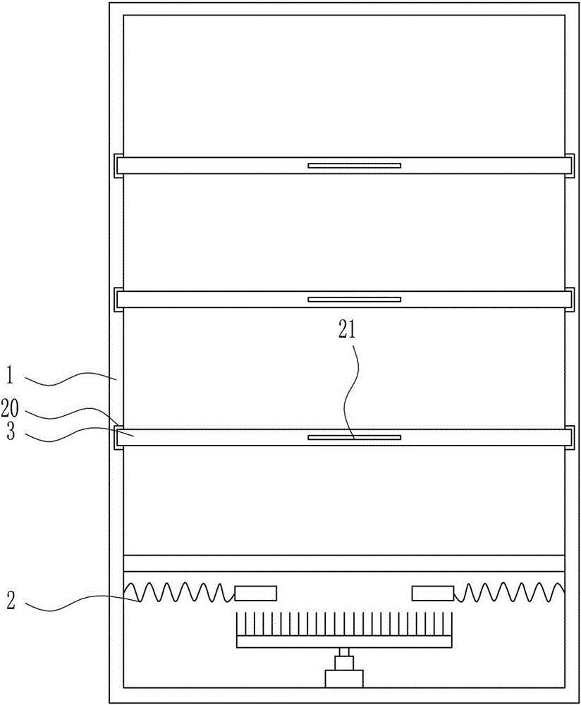
[0031] A shoe cabinet with a cleaning function, such as Figure 1-6 As shown, it includes a shoe cabinet device 1, a cleaning device 2, a placement plate 3 and a second handle 21. The bottom of the shoe cabinet device 1 is provided with a cleaning device 2, and the left and right sides of the shoe cabinet device 1 are provided with grooves 20 symmetrically. The groove 20 is located above the cleaning device 2 , and a placement board 3 is placed in the groove 20 , and a second handle 21 is provided at the front of the placement board 3 .

Embodiment 2

[0033] A shoe cabinet with a cleaning function, such as Figure 1-6 As shown, it includes a shoe cabinet device 1, a cleaning device 2, a placement plate 3 and a second handle 21. The bottom of the shoe cabinet device 1 is provided with a cleaning device 2, and the left and right sides of the shoe cabinet device 1 are provided with grooves 20 symmetrically. The groove 20 is located above the cleaning device 2 , and a placement board 3 is placed in the groove 20 , and a second handle 21 is provided at the front of the placement board 3 .

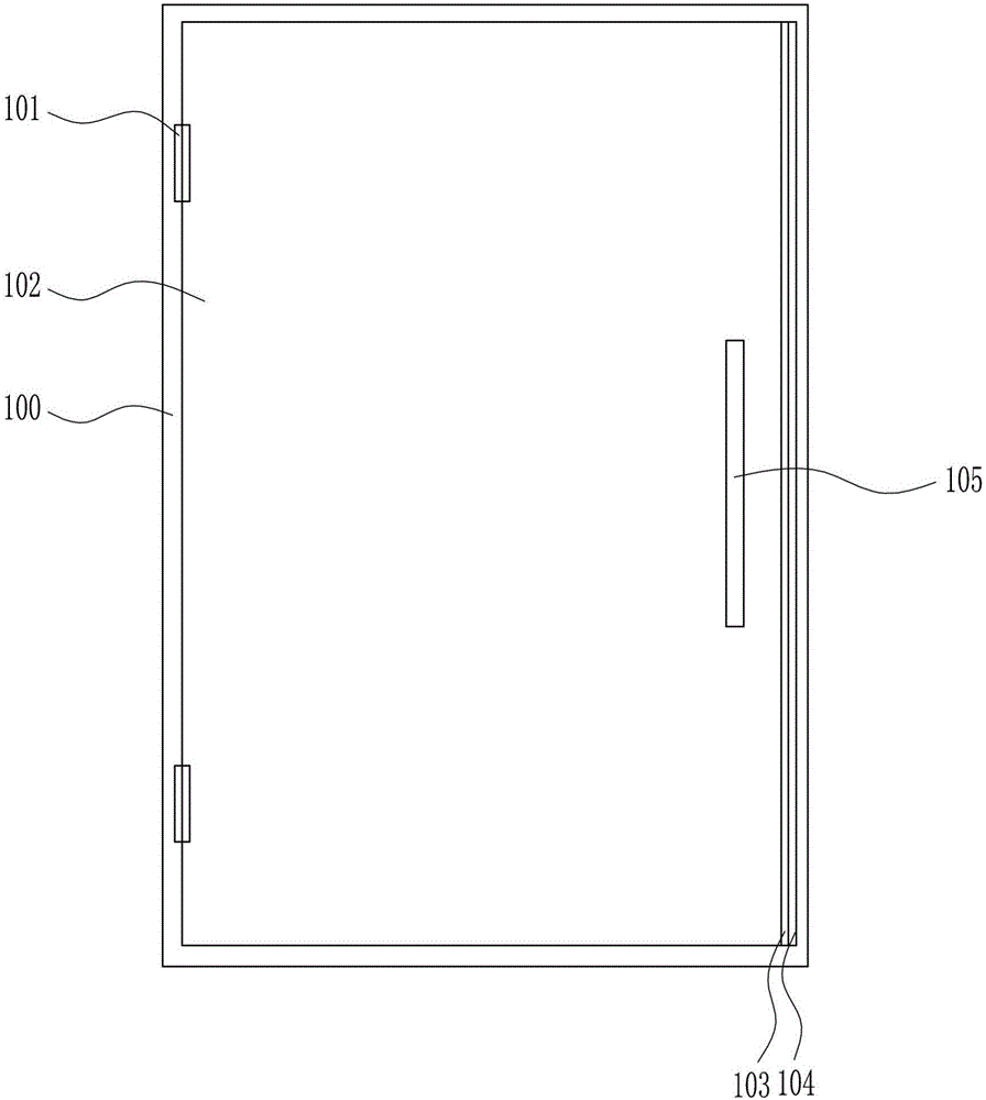
[0034] The shoe cabinet device 1 includes a first casing 100, a hinge 101, a door 102, an iron block 103, a magnet 104 and a handle 105. The right part of the page 101 is connected with a box door 102, and the right side of the box door 102 is provided with an iron block 103. A handle 105 is provided on the side.

Embodiment 3

[0036] A shoe cabinet with a cleaning function, such as Figure 1-6 As shown, it includes a shoe cabinet device 1, a cleaning device 2, a placement plate 3 and a second handle 21. The bottom of the shoe cabinet device 1 is provided with a cleaning device 2, and the left and right sides of the shoe cabinet device 1 are provided with grooves 20 symmetrically. The groove 20 is located above the cleaning device 2 , and a placement board 3 is placed in the groove 20 , and a second handle 21 is provided at the front of the placement board 3 .

[0037]The shoe cabinet device 1 includes a first casing 100, a hinge 101, a door 102, an iron block 103, a magnet 104 and a handle 105. The right part of the page 101 is connected with a box door 102, and the right side of the box door 102 is provided with an iron block 103. A handle 105 is provided on the side.

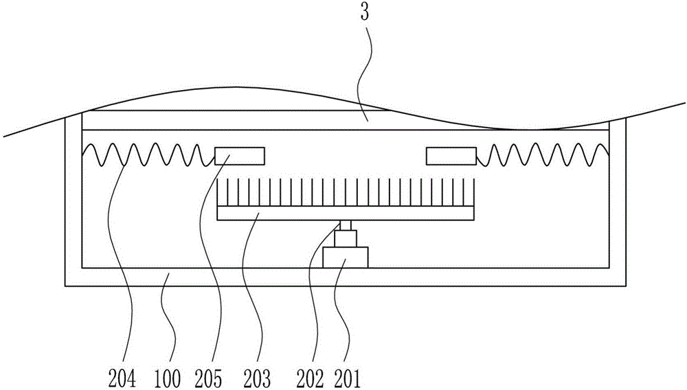
[0038] The cleaning device 2 includes a motor 201, a pole 202, a hair brush 203, a spring 204 and an arc ferrule 205. A motor 20...


PUM


Abstract

The invention relates to a shoe cabinet, in particular to a shoe cabinet with a cleaning function. In order to achieve the technical purpose that the shoe cabinet with the cleaning function is provided, the shoe cabinet with the cleaning function comprises a shoe cabinet device, a cleaning device, holding plates, second handles and the like. The cleaning device is arranged at the bottom in the shoe cabinet device, grooves are symmetrically formed in the left and right sides in the shoe cabinet device respectively, the grooves are formed above the cleaning device, the holding plates are placed in the grooves, and the second handles are arranged on the front portions of the holding plates. By means of the shoe cabinet with the cleaning function, the effects of thoroughly cleaning shoe vamps and shoe soles are achieved, the shoe soles can be scrubbed with a brush, the dust and stains on the shoe soles can be brushed away, and the dust on the surfaces of shoes can be scrubbed out through a sponge.

Description

technical field [0001] The invention relates to a shoe cabinet, in particular to a shoe cabinet with a cleaning function. Background technique [0002] The main purpose of shoe cabinets is to display idle shoes. With the progress of society and the improvement of human living standards, the early wooden shoe cabinets have evolved into shoe cabinets of various styles and materials, including wooden shoe cabinets, electronic Shoe cabinets and disinfection shoe cabinets, etc., have different functions and styles. [0003] Shoes, a kind of article worn on the feet to prevent the feet from being hurt, were mostly straw sandals and cloth shoes in the early history of human civilization, but now leather shoes and sports shoes are more common. [0004] Existing shoe cabinets have the disadvantage of being unable to clean the uppers and soles, so there is an urgent need to develop a shoe cabinet with a cleaning function. Contents of the invention [0005] (1) Technical problems t...

Claims


Application Information

Patent Timeline
Patent Type & Authority Applications(China)
IPC IPC(8): A47B61/04A47L23/02
CPCA47B61/04A47L23/02
Inventor 钮芳琴
Owner 湖州黛丝娅鞋业有限公司
Why Eureka
Try Eureka