Spiral gear limiting device

A limit device, screw-type technology, applied in gear teeth manufacturing devices, belts/chains/gears, gear teeth, etc., can solve problems such as pressure dispersion

Active Publication Date: 2017-05-31
CHONGQING SUTENG MACHINERY MFG
View PDF7 Cites 0 Cited by
  • Summary
  • Abstract
  • Description
  • Claims
  • Application Information

AI Technical Summary

Problems solved by technology

[0004] The purpose of the present invention is to provide a helical gear limiting device to solve the problem of the pressure dispersion of the fixed element group on the inner ring side of the gear when the gear is fixed in the prior art

Method used


Image

  • Spiral gear limiting device
  • Spiral gear limiting device

Examples


Embodiment

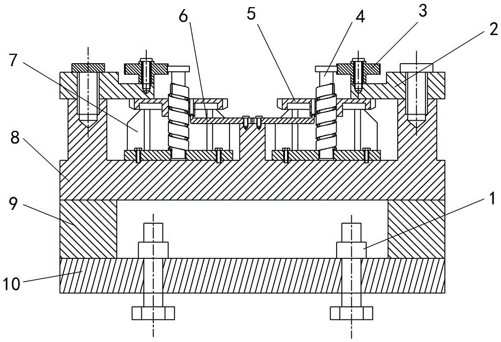
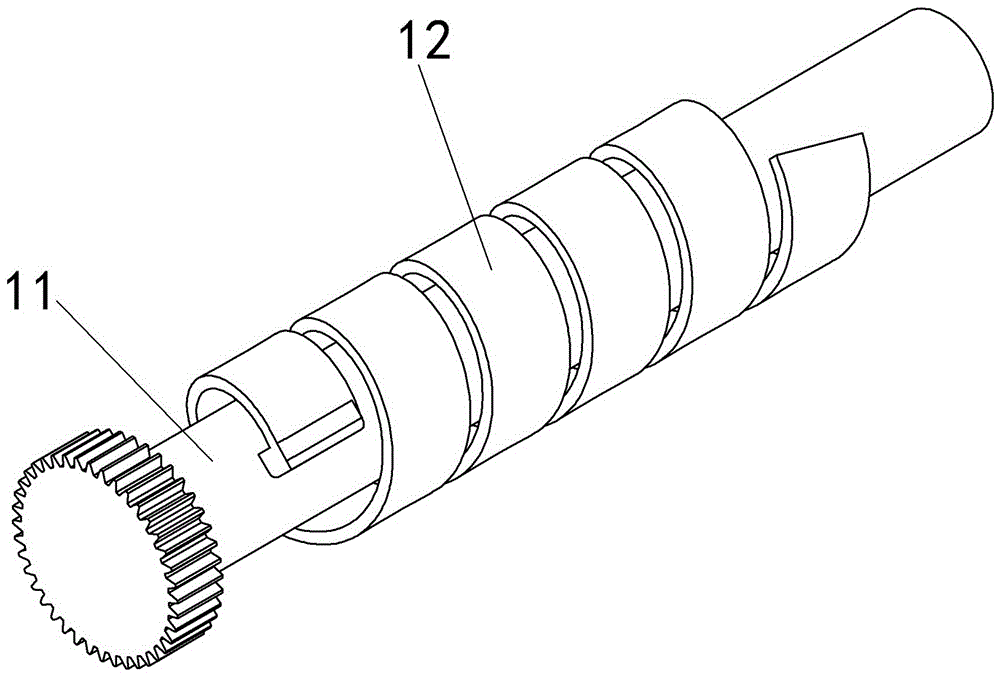
[0017] Example: such as figure 1 , The helical gear limiting device in this technical solution includes a base and a clamp assembly installed on the base. There are six sets of clamp assemblies on the base, distributed in a 2×3 matrix. The base is composed of an upper base plate 8, a lower base plate 10, and a backing plate 9 arranged between the upper and lower base plates 10. The upper base plate 8 and the lower base plate 10 are connected together by screws, and the outer periphery of the base plate is provided with lifting bolts. The lower base plate 10 is provided with T-bolt 1 for connecting the machine tool. The clamp assembly includes a gear 5 supporting seat 7, a fixed element group 4, a positioning block 6, and a pressure block 2. The supporting seat 7 is in the shape of a disk, and the outer circumference of the disk extends upwards with pillars arranged at intervals. The support seat 7 is fixedly installed on the base, and the top of the support seat 7 is horizont...


PUM


Abstract

The invention belongs to the field of workpiece clamping devices, and in particular, discloses a spiral gear limiting device. The spiral gear limiting device comprises a base, and a fixture combination mounted on the base; the fixture combination includes a gear support base, a fixed element set, a positioning block and a pressing block; the positioning block is clamped in a key slot of a gear; the fixed element set includes a pin and a spiral bar; the other end of the spiral bar is fixed on the support base; the spiral bar extends from bottom to top along the outer periphery of the pin; the outer side edge of the spiral bar is parallel to the center line of the pin; one end of the spiral bar is fixed on the pin; and the pin is positioned in the center of the support base. The spiral gear limiting device solves the problem of dispersion of lateral pressure of the inner ring of the gear by the fixed element set in gear fixation in the prior art, and reduces the equipment cost.

Description

technical field [0001] The invention belongs to the field of workpiece clamping devices. Background technique [0002] At present, when drilling the end face of gears, paired gears are often used to determine the tooth shape, and the fixture itself cannot be tested. The fixture can only be adjusted according to the actual measurement of the processed product. After adjustment, the positioning gear is fixed by welding. The welded fixture is deformed due to internal stress, the use of the fixture is very unstable, the debugging of the fixture takes a long time, the product quality is unstable, and the pass rate is low. [0003] The patent document with the authorized notification number CN102275080B discloses a device including a base and a clamp assembly installed on the base, the clamp assembly includes a support seat, a positioning block, an elastic sleeve, a pull rod, a positioning pin, a pressing block and Positioning pin seat, a gear is placed horizontally above the sup...

Claims


Application Information

Patent Timeline
Patent Type & Authority Applications(China)
IPC IPC(8): B23F23/06
Inventor 王全中
Owner CHONGQING SUTENG MACHINERY MFG
Why Eureka
Try Eureka