
Gear drilling clamp

A drilling fixture and gear technology, applied in the field of workpiece clamping devices, can solve problems such as pressure dispersion and achieve the effect of simple structure

Inactive Publication Date: 2017-05-17
CHONGQING SUTENG MACHINERY MFG
View PDF7 Cites 1 Cited by
  • Summary
  • Abstract
  • Description
  • Claims
  • Application Information

AI Technical Summary

Problems solved by technology

[0004] The purpose of the present invention is to provide a device to solve the problem of the pressure distribution of the fixed element group on the inner ring side of the gear when the gear is fixed in the prior art

Method used


Image

  • Gear drilling clamp
  • Gear drilling clamp
  • Gear drilling clamp

Examples


Embodiment

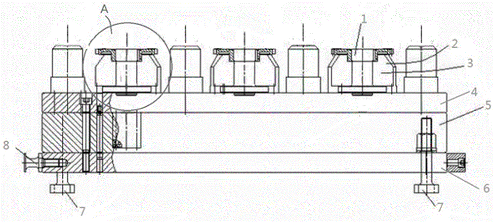
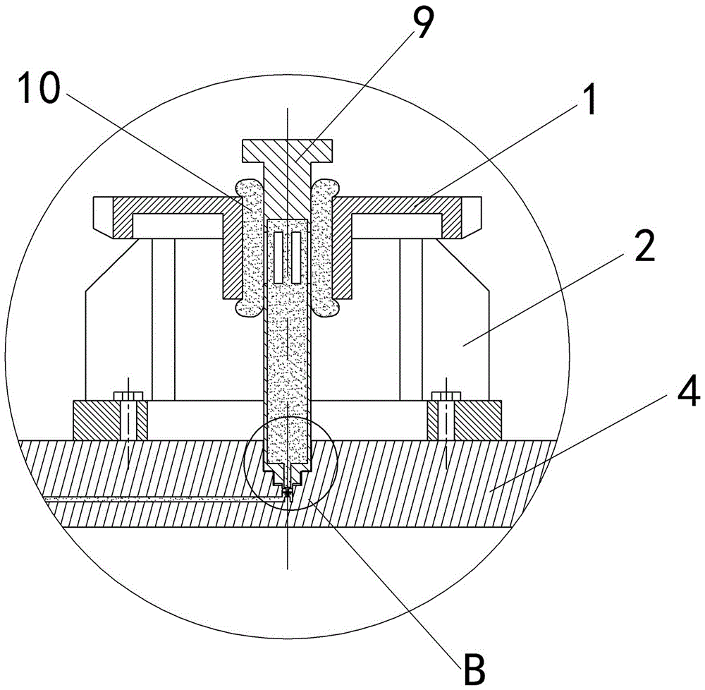
[0021] Example: such as figure 1 As shown, the gear drilling fixture in this technical solution includes a base. There are six stations arranged in a 2x3 matrix on the base. Each station is equipped with a fixture combination. The base consists of an upper base plate 4, a lower base plate 6, and A backing plate 5 between the upper and lower bottom plates 6 is formed. The upper bottom plate 4 and the lower bottom plate 6 are connected together by screws, and the outer periphery of the bottom plate is provided with a lifting bolt 8. The drilling fixture is installed on the machine tool, and a T-slot quick-release bolt is arranged under the base for connection with the machine tool. The clamp assembly includes a supporting base 3 and a fixing element group. The supporting base 3 is screwed on the base. The supporting base 3 is in the shape of a disc. The outer periphery of the disc is extended with pillars 2 arranged at intervals. The supporting base 3 is screwed on the base, and ...


PUM


Abstract

The invention belongs to the field of workpiece clamping devices, and particularly discloses a gear drilling clamp which comprises a base and a clamp assembly mounted on the base, wherein the clamp assembly comprises supporting seats and fixing element groups; gears are horizontally placed above the supporting seats; the fixing element groups comprise hollow pins and oil sacs; oil outlets are arranged on the hollow pins; the lower parts of the hollow pins serve as oil inlet structures; the oil sacs are fixed on the circumferential walls of the hollow pins; the oil sacs and the hollow pins communicate through the oil outlets; the perpendicular length of each oil sac is greater than the thickness of each gear; insertion holes corresponding to the oil inlet structures are formed in the base; the fixing elements groups penetrate through the gears from top to bottom, and then are fixed in the insertion holes; and oil channels are arranged in the base and lead to the insertion holes. By adoption of the gear drilling clamp disclosed by the invention, the problem that in the prior art, the inner gear ring side pressure is dispersed by a fixing element group under the presence of a fixing gear can be solved. Compared with the prior art, the gear drilling clamp is simple in structure.

Description

Technical field [0001] The invention belongs to the field of workpiece clamping devices. Background technique [0002] At present, when drilling gear end holes, matching gears are often used to fix the tooth profile, and the fixture itself cannot be tested. The fixture can only be adjusted according to the actual measurement of the processed product. After the adjustment, the positioning gear is fixed by welding. The welded fixture is deformed due to internal stress, the fixture use process is very unstable, the debugging fixture time is long, the product quality is unstable, and the pass rate is low. [0003] The patent document with the authorized announcement number CN102275080B discloses a device including a base and a clamp assembly installed on the base. The clamp assembly includes a support seat, a positioning block, an elastic sleeve, a tie rod, a positioning pin, a pressing block, and A positioning pin seat, a gear is horizontally placed above the support seat, the positi...

Claims


Application Information

Patent Timeline
IPC IPC(8): B23Q3/08
CPCB23Q3/082B23Q2703/04
Inventor 王全中
Owner CHONGQING SUTENG MACHINERY MFG
Features
  • Generate Ideas
  • Intellectual Property
  • Life Sciences
  • Materials
  • Tech Scout
  • Unparalleled Data Quality
  • Higher Quality Content
  • 60% Fewer Hallucinations
Learn More