An industrial automatic palletizing robot

A palletizing robot and automatic technology, which is applied in the direction of object depalletizing, object stacking, transportation and packaging, etc., can solve the problems of low palletizing efficiency, short operation time, slow palletizing speed, etc., and achieve palletizing efficiency High efficiency, short operation time and fast palletizing speed

Active Publication Date: 2019-04-16
BEIJING C H L ROBOTICS CO LTD
View PDF9 Cites 1 Cited by
  • Summary
  • Abstract
  • Description
  • Claims
  • Application Information

AI Technical Summary

Problems solved by technology

[0003] In order to solve the above problems, the present invention provides an industrial automatic palletizing robot, which can solve the problems of high labor intensity, long operation time, slow palletizing speed, low palletizing efficiency and the risk of scalding existing in the manual palletizing mode of existing high-temperature forgings. It can realize the automatic palletizing function of high-temperature forgings without manual operation, and has the advantages of short operation time, fast palletizing speed, high palletizing efficiency, no safety hazard of burns and high work efficiency due to problems such as large coefficient and low work efficiency.

Method used


Image

  • An industrial automatic palletizing robot
  • An industrial automatic palletizing robot
  • An industrial automatic palletizing robot

Examples


Embodiment Construction

[0022] In order to make the technical means, creative features, goals and effects achieved by the present invention easy to understand, the present invention will be further described below in conjunction with specific illustrations.

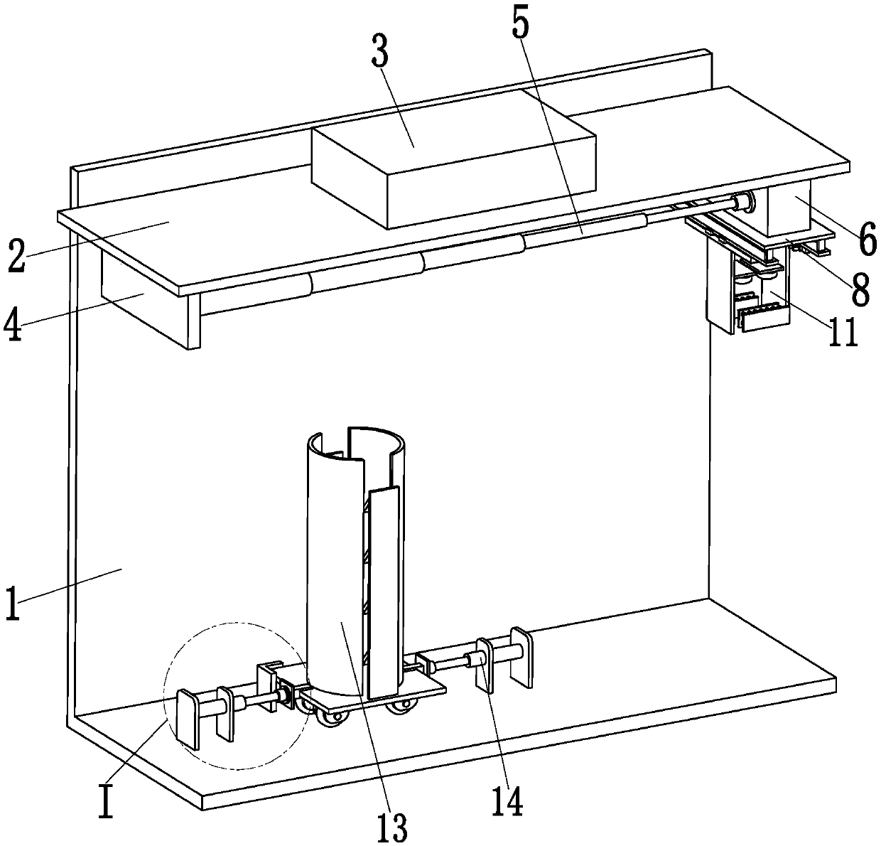
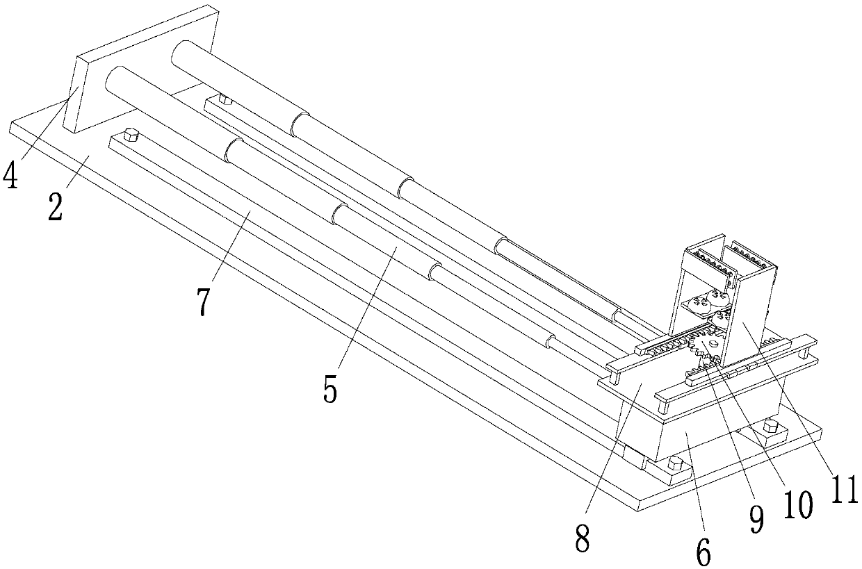
[0023] Such as Figure 1 to Figure 5 As shown, an industrial automatic palletizing robot includes a fixed frame 1, a fixed plate 2 is installed on the upper end of the front side of the fixed frame 1, and a control system 3 is installed on the upper end of the fixed plate 2, and the control system 3 controls this The invention automatically stacks high-temperature forgings. A vertical plate 4 is provided on the left side of the lower end of the fixed plate 2. A horizontal drive mechanism is arranged on the inner wall of the vertical plate 4 along the horizontal direction. In this embodiment, the horizontal drive mechanism is symmetrically installed on the Two stroke hydraulic cylinders 5 on the inner wall of the vertical plate 4 are composed, th...


PUM


Abstract

The invention relates to an industrial automatic stacking robot which comprises a fixing rack. A fixing plate is installed at the upper end of the front side face of the fixing rack, a control system is installed on the upper end face of the fixing plate, and the industrial automatic stacking robot is controlled by the control system to automatically stack high temperature forge pieces; a vertical plate is arranged on the left side of the lower end of the fixing plate, two stroke hydraulic cylinders are symmetrically installed on the inner wall of the vertical plate, installation bases are installed at the top ends of the two stroke hydraulic cylinders through flanges, the upper end faces of the installation bases are symmetrically installed on two linear sliding rails, and the two linear sliding rails are symmetrically installed on the lower end face of the fixing plate; and a clamping table is installed on the lower end face of the installation base, a driving motor is installed at the middle portion of the lower end face of the clamping table through a motor base, a driving gear is installed at an output shaft of the driving motor, and two forge piece clamping mechanisms are meshed to the two sides of the driving gear. By means of the industrial automatic stacking robot, the automatic stacking function of the high temperature forge pieces can be achieved, and manual operation is not needed.

Description

technical field [0001] The invention relates to an industrial robot, in particular to an industrial automatic palletizing robot. Background technique [0002] With the continuous development of my country's economy and the rapid advancement of science and technology, robot palletizing has been widely used in logistics, production lines, supermarkets and other industries. High-temperature forgings produced by forging plants have always been a technical difficulty in robot automatic palletizing due to factors such as high temperature, difficulty in rapid cooling, and manual operation. The forgings in existing forging plants are all manually stacked. The manual palletizing method has the following defects: 1. Since the temperature of the forgings is high when they are just out of the furnace, it takes a long cooling time before they can be manually palletized. The operation time is long and the work efficiency is low; There is still a temperature of hundreds of degrees Celsius...

Claims


Application Information

Patent Timeline
Patent Type & Authority Patents(China)
IPC IPC(8): B65G61/00
CPCB65G61/00
Inventor 蔡惠芳
Owner BEIJING C H L ROBOTICS CO LTD
Why Eureka
Try Eureka