Automatic heat dissipation angle adjustable PAR lamp

An angle-adjustable and adjustable technology, used in lighting and heating equipment, cooling/heating devices for lighting devices, lighting devices, etc., can solve the problem that the cooling fan cannot start and stop independently, shorten the service life of the cooling fan, and accelerate the light decay of LED lamp beads. and other problems to achieve the effect of reducing temperature, increasing service life and long service life

Inactive Publication Date: 2017-05-31
UNIV OF ELECTRONICS SCI & TECH OF CHINA ZHONGSHAN INST
View PDF13 Cites 2 Cited by
  • Summary
  • Abstract
  • Description
  • Claims
  • Application Information

AI Technical Summary

Problems solved by technology

[0003] In the existing technology, due to the small structure of PAR lamps, the maximum power can only be 18W under normal circumstances, otherwise the heat generated by the lamp beads cannot be exported, which will lead to faster pearlescent decay of LED lamps and short lamp life. Lamps (20-40W) are in great demand, so fans must be added to the original basis to actively dissipate heat to ensure the normal life of the lamps and open up this market. Although there are PAR lamps with cooling functions on the market, their cooling effect is not good, and cooling fans It cannot be turned on and off independently, thus shortening the service life of the cooling fan. When the internal temperature of the PAR lamp is low, the cooling fan is always working, which is a waste of electric energy. At the same time, it is necessary to adjust the irradiation angle of the PAR lamp to achieve the required Lighting effect, this is also one of the shortcomings of existing PAR lamps, it is difficult to meet people's needs for PAR lamps, so there is an urgent need for an automatic heat dissipation angle adjustable PAR lamp to solve the above problems

Method used


Image

  • Automatic heat dissipation angle adjustable PAR lamp
  • Automatic heat dissipation angle adjustable PAR lamp
  • Automatic heat dissipation angle adjustable PAR lamp

Examples


specific Embodiment approach

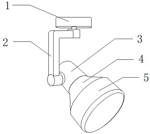
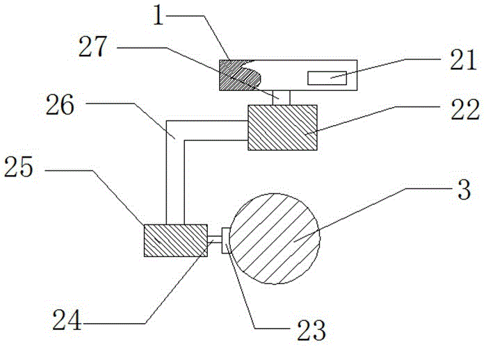
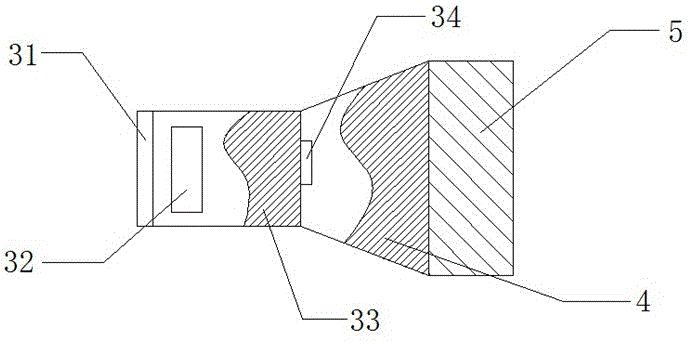
[0024] Specific embodiments: the user connects the present invention with an external power supply, the external power supply transmits electric energy to the storage battery 21, the storage battery 21 stores the electric energy inside, and the storage battery 21 transmits electric energy to the first motor 22 and the second motor 25, and the first motor 22 Electric energy is converted into mechanical energy with motor two 25, because motor one 22 is connected with mounting disc 1 by transmission shaft one 27, so motor one 22 itself rotates in the horizontal direction, and motor one 22 drives L-shaped connecting rod 26 in horizontal direction Rotate, make the present invention can rotate 360 ​​degrees, simultaneously motor 2 25 transmits mechanical energy to connection plate 23 by transmission shaft 2 24, makes connection plate 23 rotate in vertical direction, and connection plate 23 drives cooling chamber 33 in vertical Rotate vertically, so that the light emitted by the PAR l...


PUM


Abstract

The invention provides an automatic heat dissipation angle adjustable PAR lamp which comprises a first motor, a first transmission shaft, a second motor, an L-shaped connecting rod, a second transmission shaft, a heat dissipation opening, a heat dissipation fan, a heat dissipation chamber and a temperature control switch. The lower end of the first transmission shaft is assembled in the first motor. The upper end of the L-shaped connecting rod is mounted on the outer surface of the first motor, and the lower end of the L-shaped connecting rod is mounted on the outer surface of the second motor. The left end of the second transmission shaft is assembled in the second motor. By means of the design, the problem of the single irradiation angle of an original PAR lamp is solved, and the range of the irradiation angle of the automatic heat dissipation angle adjustable PAR lamp is expanded; the heat dissipation fan is assembled in the heat dissipation chamber, the heat dissipation opening is mounted on the lower end face of the heat dissipation chamber, and the temperature control switch is connected with the heat dissipation fan through a wire; by means of the design, the problem of the short service life of the PAR lamp is solved, the temperature in the PAR lamp is effectively reduced, energy is saved, and automatic starting and stopping of the heat dissipation fan are achieved; and the automatic heat dissipation angle adjustable PAR lamp is convenient to mount, saves energy and is long in service life and low in maintenance efficiency.

Description

technical field [0001] The invention is a PAR lamp with an adjustable automatic cooling angle, which belongs to the field of lamps. Background technique [0002] PAR lamp is also called downlight. Its structure is to install a mirror bulb in a cylinder or use a reflective bowl to hold a bromine tungsten bulb. The main feature is that it emits a relatively fixed beam with various beam angles. The spot size cannot be adjusted. [0003] In the existing technology, due to the small structure of PAR lamps, the maximum power can only reach 18W under normal circumstances, otherwise the heat generated by the lamp beads cannot be exported, which will lead to accelerated pearl light decay of LED lamps and short lamp life. The demand for lamps (20-40W) is large, so it is necessary to increase the active cooling of the fan on the original basis to ensure the normal life of the lamps and open up this market. Although there are PAR lamps with heat dissipation function on the market, their...

Claims


Application Information

Patent Timeline
Patent Type & Authority Applications(China)
IPC IPC(8): F21S9/02F21V14/02F21V21/28F21V29/67F21V7/04
CPCF21S9/02F21V7/04F21V14/02F21V21/28F21V29/67
Inventor 石世光骆昊
Owner UNIV OF ELECTRONICS SCI & TECH OF CHINA ZHONGSHAN INST
Why Eureka
Try Eureka