Bifocal positioning-free ellipsoidal reflector lighting device

A technology for ellipsoidal reflectors and lighting devices, applied in measuring devices, optical devices, instruments, etc., can solve problems such as complicated methods, low efficiency, and reduced complexity of ellipsoidal reflector systems

Active Publication Date: 2019-07-09
HARBIN INST OF TECH
View PDF5 Cites 0 Cited by
  • Summary
  • Abstract
  • Description
  • Claims
  • Application Information

AI Technical Summary

Problems solved by technology

However, this measurement method is inefficient and complicated, and for the near focus of the ellipsoidal mirror, the traditional measurement method cannot solve the problem
If the complex three-dimensional measurement of space can be avoided when designing the ellipsoidal mirror system, the complexity of the measurement of the ellipsoidal mirror system will be greatly reduced

Method used


Image

  • Bifocal positioning-free ellipsoidal reflector lighting device
  • Bifocal positioning-free ellipsoidal reflector lighting device

Examples


specific Embodiment 1

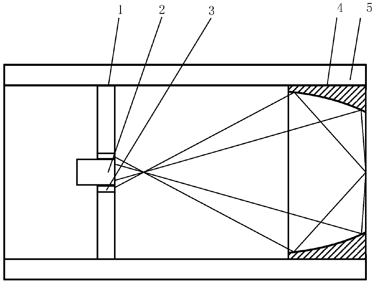
[0028] The structure schematic diagram of the bifocal positioning-free ellipsoid reflector lighting device of this embodiment is as follows figure 1 shown. The bifocal positioning-free ellipsoid reflector lighting device includes a coaxially arranged fixed disk 1, an objective lens 2, an objective lens adapter 3, an ellipsoid reflector 4 and a fixed sleeve 5;

[0029] The fixed disk 1 is installed inside the fixed sleeve 5, and the center of the fixed disk 1 has a threaded hole, and the objective lens adapter 3 for fixing the objective lens 2 is threadedly connected with the threaded hole, and the objective lens is realized by rotating in the threaded hole. 2. Move on the optical axis so that the focal point of the objective lens 2 coincides with the far focal point of the ellipsoidal reflector 4;

[0030] The near focal point of the ellipsoid reflector 4 is located on the end surface of the ellipsoid reflector 4 and the end surface of the fixed sleeve 5 at the same time.

specific Embodiment 2

[0032] The bifocal positioning-free ellipsoid reflector lighting device of the present embodiment, on the basis of the specific embodiment 1, further defines that the focal point of the objective lens 2 coincides with the far focus of the ellipsoid reflector 4, and the adjustment steps and judgment methods are as follows:

[0033] Step a, place a point light source at the near focal point of the ellipsoidal reflector 4, and place an observation screen or an imaging device behind the objective lens 2;

[0034] Step b, screwing the objective lens adapter 3 to move the objective lens 2 on the optical axis;

[0035] In step c, when the light intensity of the circular spot on the observation screen or the imaging device reaches the maximum value, the focal point of the objective lens 2 coincides with the far focal point of the ellipsoidal reflector 4 .

specific Embodiment 3

[0037] The bifocal positioning-free ellipsoid reflector lighting device of the present embodiment, on the basis of the specific embodiment 1, further defines that the focal point of the objective lens 2 coincides with the far focus of the ellipsoid reflector 4, and the adjustment steps and judgment methods are as follows:

[0038] Step a, place a point light source at the near focal point of the ellipsoidal reflector 4, and place an observation screen or an imaging device behind the objective lens 2;

[0039] Step b, screwing the objective lens adapter 3 to move the objective lens 2 on the optical axis;

[0040] Step c. Move the observation screen or imaging device on the optical axis. When the size of the circular light spot on the observation screen or imaging device remains unchanged, the focal point of the objective lens 2 coincides with the far focus of the ellipsoidal mirror 4 .


PUM


Abstract

The invention provides a bifocal positioning-free ellipsoid-surface reflector lighting device and belongs to the technical field of optical microscopic lighting. The lighting device includes a fixed plate, an objective lens, an objective-lens adapting part, an ellipsoid-surface reflector and a fixed sleeve, wherein the fixed plate, the objective lens, the objective-lens adapting part, the ellipsoid-surface reflector and the fixed sleeve are coaxially arranged; the fixed plate is installed in the fixed sleeve, the center of the fixed plate is provided with a threaded hole for fixedly connecting the objective-lens adapting part of the objective lens with threads of the threaded hole, and when the objective-lens adapting part rotates in the threaded hole, the objective lens moves on an optical axis to make the focus of the objective lens overlapped with the apofocus of the ellipsoid-surface reflector; the perifocus of the ellipsoid-surface reflector is located on the end face of the ellipsoid-surface reflector and on the end face of the fixed sleeve at the same time; by a specific mechanical structure design, the lighting device avoids the three-dimensional measurement of spaces, and achieves the technical purpose that the ellipsoid-surface reflector does not need positioning.

Description

technical field [0001] The bifocal positioning-free ellipsoid reflector lighting device of the invention belongs to the technical field of optical microscopic lighting. Background technique [0002] With the development of microscopic technology, reflective microscopic imaging system has been paid more and more attention. The structures capable of imaging at large numerical aperture angles are: parabolic mirrors, hyperbolic mirrors and ellipsoidal mirrors. Among them, ellipsoidal mirrors are widely used in optical confocal microscopy due to their advantages of increasing numerical aperture and enhancing contrast. In the field of technology and optical precision measurement technology, for example, the invention patent with application number 201210244377.2 "Confocal measurement device based on ellipsoidal reflection illumination". [0003] However, the ellipsoidal mirror has a large collection aperture angle, which requires very high accuracy of assembly and adjustment, and...

Claims


Application Information

Patent Timeline
Patent Type & Authority Patents(China)
IPC IPC(8): G01B9/04
CPCG01B9/04
Inventor 刘俭李梦周李强高姗谭久彬
Owner HARBIN INST OF TECH
Why Eureka
Try Eureka